6
DRIVEN ELEMENT ASSEMBLY
This completes assembly of the driven element. Check to see that all hardware is tight but do not over
tighten the clamps and bend them out of shape. Set the driven element aside.
REFLECTOR ASSEMBLY
In the following steps you will complete assembly of the reflector element. Again, use a light coating of
anti-oxide compound where clamps attach to tubes or rods.
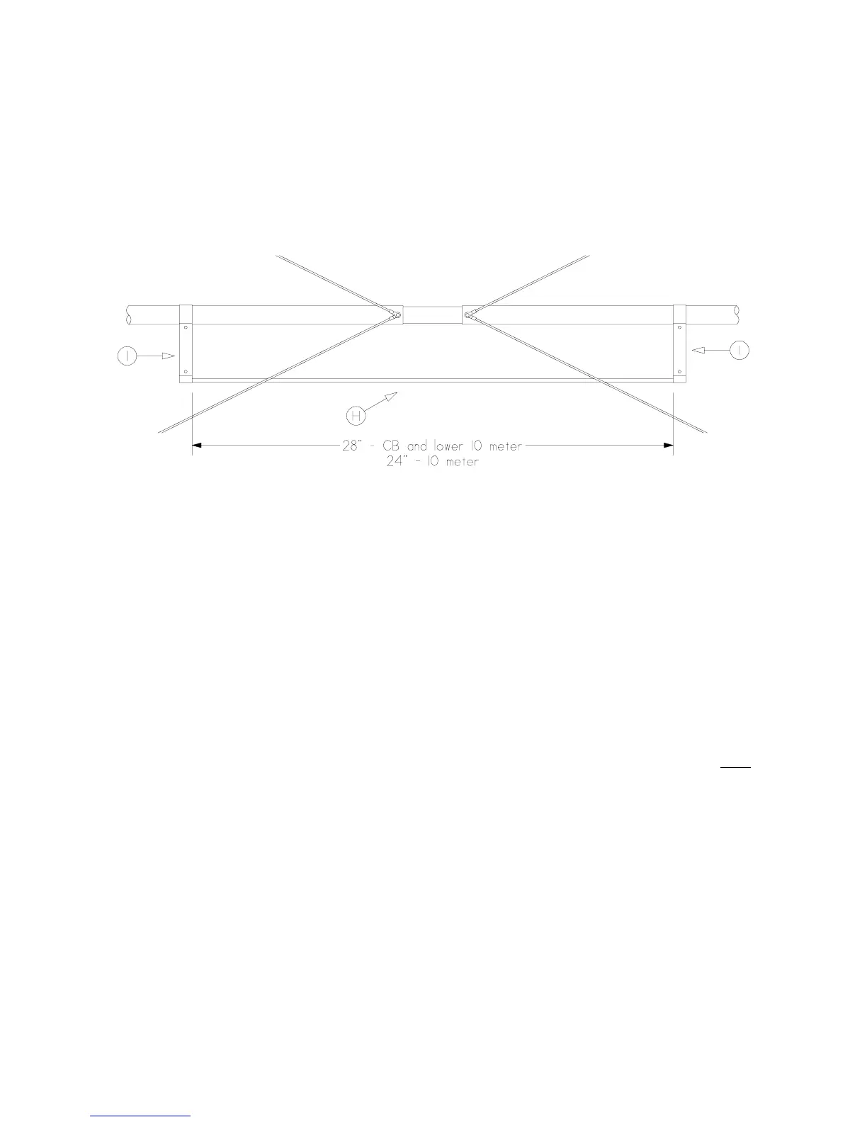
1. Find rod (H) and two clamps (I). Attach the clamps (I) to the rod (H) as shown using 3/4" bolts (X),
lock washers (BB) and hex nuts (AA).
2. Attach the above assembly to the tubes (A) as shown, using 1 1/4" bolts (Z), lock washers (BB) and
hex nuts (AA). Make sure the assembly is centered and rod (H) does not contact spreader wires (D).
REFLECTOR ASSEMBLY
This completes assembly of the reflector. Check all hardware to be sure that it is tight, but do not over
tighten the clamps and bend them out of shape.
FINAL ASSEMBLY
Whether the antenna is to be carried to its final destination atop the supporting structure in one piece or
several pieces, whether the structure is supported by guy wires, etc. depends on your particular installa-
tion. The Butterfly™ beam is not very heavy, but it can be hard to handle if you have to hold it with one
hand while trying to snake it past guy wires while holding on for dear life! A good safety belt is a must
for tower work. Be sure that the tower can support the weight of the antenna, rotating system and the
weight of the person doing the installation. For the sake of safety, be guided by the recommendations of
the tower manufacture
and such information as may be found in the American Radio Relay League Handbook, the A.R.R.L.
Antenna Book and other publications relating to the installation of antenna systems. Before installing,
you should consult local and national electrical codes as well as local ordinances relating to such struc-
tures.
WARNING: UNDER NO CIRCUMSTANCES SHOULD THE ANTENNA BE INSTALLED IN
ANY PLACE WHERE IT CAN COME INTO CONTACT WITH POWER LINES DURING IN-
STALLATION, NORMAL OPERATION, REMOVAL OR IN THE EVENT OF MECHANICAL
FAILURE OF THE ANTENNA OR ITS SUPPORTING STRUCTURE. NOR SHOULD THE
ANTENNA BE INSTALLED IN ANY PLACE WHERE STRUCTURAL FAILURE CAN
RESULT IN DAMAGE OR INJURY TO PERSONS.
The following detail show the way the two elements are attached to tube (L).
1. Locate the boom to element plates (N), u-bolts (O) and u-bolts (P).
 Loading...