831 North Central Avenue Wood Dale Illinois 60191-1219 Telephone 630@238@1183 Facsimile 630@238@1186 www.bencher.com
VI00159Z 080899-1-
Instructions
Model HF5B
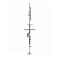
Butternut presents the model HF5B BUTTERFLY compact beam antenna for the 10, 12, 15, 17, and 20
meter amateur bands! With elements only 12 ft 6 in (3.8 m) long and a turning radius under 7 ft (2.1 m), it
presents a low profile that allows it to be used in areas where other beam antennas would be restricted.
High-efficiency design and broad-band BUTTERFLY elements deliver performance expected only in
much larger designs.
SPECIFICATIONS
WINGSPAN:
12 ft 6 in (3.8 m)
BOOM LENGTH:
6 ft (1.8 m)
TURNING RADIUS: 6 ft 11 in (2.1 m)
VERTICAL SPREADERS: 6 ft (1.8 m)
SHIPPING WEIGHT: 22 lbs (10 kg)
FEED POINT IMPEDANCE:
Nominal 50 ohms. Includes RF connector for direct connection to any
length feed line terminated in PL-259
VSWR AT RESONANCE: 1.5:1 or less on all bands
POWER RATING: 1200 W PEP
WIND LOADING: 3 ft
2
(.3 m
2
)
WIND SURVIVAL:
80 mph (129 kph)
BANDWIDTH:
VSWR 2:1 or less 1.5 MHz on 10 meters; entire band on 12, 15 and
17 meters; 200 kHz on 20 meters
GAIN: 3+ dBd 20 meters, up to 5 dBd other bands except 17 meters where
antenna acts as rotary dipole.
FRONT-TO-BACK:
Up to 20 dB
FRONT-TO-SIDE:
Up to 30 dB
TUNING SYSTEM: No traps; entire element length active on all bands; no tuner required.
MINIMUM RECOMMENDED
HEIGHT ABOVE GROUND: 30 ft (9.1 m)
Accepts up to 1 1/2 in (38.1 mm) mast. Light enough to be turned with a TV rotator.