-20-
FINAL TUNING
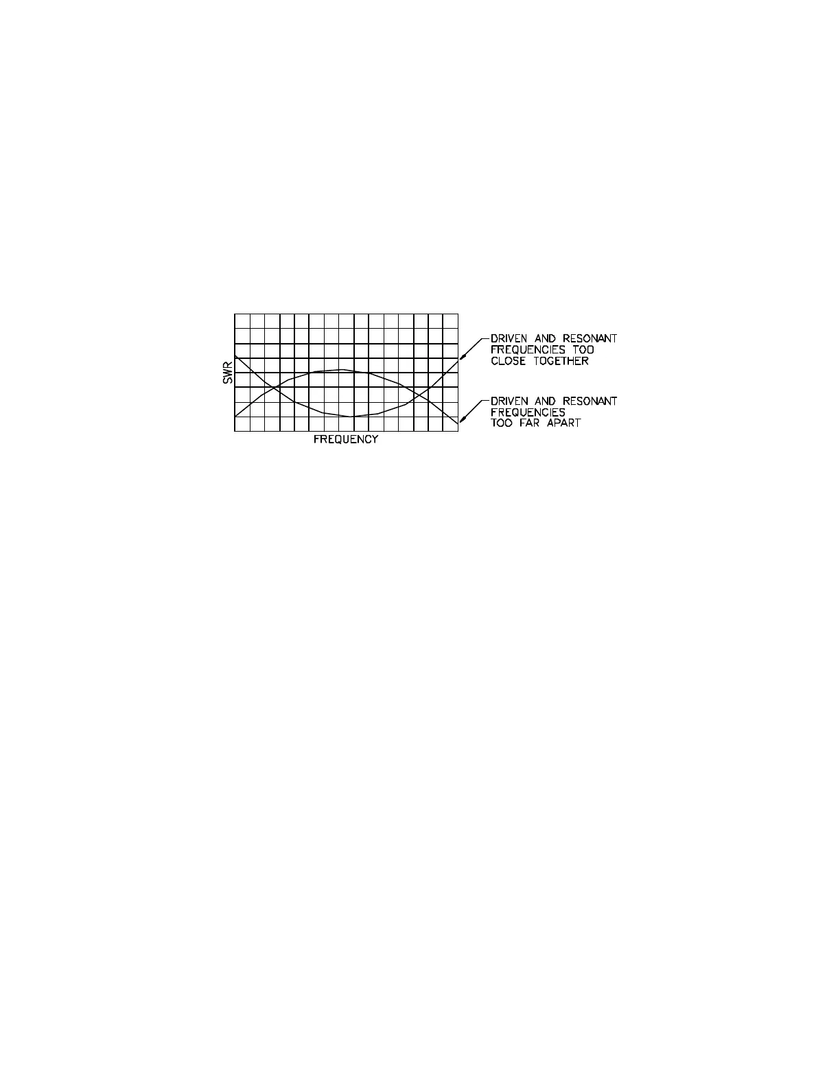
F/B rejection will occur only over the LOWER, part of the SWR curve (the dip on the left), and will be
greatest when the difference between the dips is 150-200kHz. When the two dips are close together,
they tend to blend into a single broad dip, especially when the antenna is close to the ground. The
advantages of seeking the "double-dip" SWR curve is that its presence indicates a condition where the
antenna is tuned for reasonably good F/B rejection and that the operator may observe the effect of
adjustments made to the elements.
In any case, the proper procedure is to adjust for 20 meters first, then for 15 meters, 10 meters, 12 meters
and finally 17 meters. Remember, as before, it is assumed that you are viewing the element from the
tower, sighting along the boom from the mast. Tuning adjustments for 20 meters are made to the LEFT
side of each element while those for 15/10 meters are made on the RIGHT side. 15/10 meter tuning is
interlocked to some extent, but separate adjustments for 10 is usually not necessary as tuning is quite
broad on that band.
If the preliminary settings do not produce SWR curves on 10, 15, and 20 meters similar to those in Table
1, it may be necessary to modify those settings. Remember, however, that the evils of SWR greater that
1:1 have been grossly exaggerated in recent years and that time and effort spent in tedious adjustments to
achieve the lowest possible SWR on a given band will usually produce no noticeable improvement in one's
signal at a distant point! If the preliminary settings result in an SWR of, say 2:l or less over the intended
operating range, and if the transmitter is capable of delivering its rated power to the load represented by
the feed line and antenna system, adjustment for lower SWR will probably not be worth the extra time
and effort.
ROOFTOP INSTALLATIONS
Even though one has a high roof that seems suitable for the purpose of installing antennas, some cautions
should be observed. Wiring or other conductors in the attic or immediately under the roof covering can
become coupled to the antenna and affect its performance to a marked extent. Metal flashing under
shingles, rain gutters and other antennas and their feedlines, can all cause problems such as high SWR
and loss of F/B rejection, as can the beam's feed line if it can’t be run straight down from the antenna for
a quarter-wavelength or more before it has to run off in another direction. Unfortunately, some of these
problems can remain unseen or inaccessible, and there may be no cure for them short of relocating the
beam. If SWR changes significantly as the beam is rotated you should suspect some conductor or mass
of metal that you've overlooked.
USING HIGH POWER
The HF5B is rated at 1,200 watts PEP input power to the final amplifier. Exceeding this power level can
cause serious damage to the antenna. Avoid "pushing" this limit by a few hundred watts. To avoid
exceeding power limits, calculate INPUT power by multiplying AMPS times VOLTS on the amplifier's
meter, and adding feedthrough power for grounded-grid operation. THIS TOTAL SHOULD NOT BE
MORE THAN 1000 WATTS D.C.! DO NOT RELY ON A WATTMETER PLACED IN THE LINE