-19-
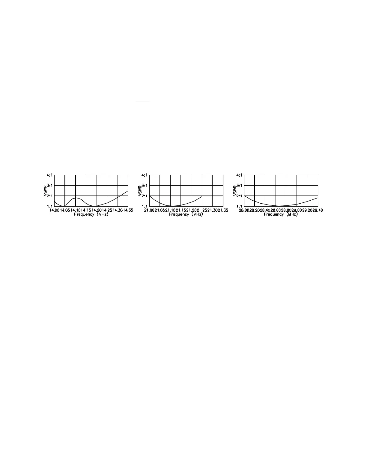
Figure 1
FINAL TUNING
meters, where the 12 ft 6 in (3.8 m) elements represent only a small fraction of a wavelength. When
bandwidth is narrow, it is impossible "cookbook" the antenna by setting it according to the suggested
starting dimensions, then installing it on a push-up mast, where it will be unreachable for tuning! Be
prepared to do some tuning, even though you have set the antenna up per the instructions!
Note: Tuning adjustments for the driven element on 20 meters are made by changing the length of the 20
meter stub (M). Tuning for 15 and 10 meters involves moving the 4-way clamp assembly on the other
side of the element. Tuning on 17 and 12 meters is largely a matter of choosing the right length of rod or
coil lead where indicated, although slight compression or expansion of the 17 meter coil may be a more
convenient way to change circuit inductance on that band. All other driven clement dimensions should be
considered fixed for all bands and tuning conditions. Please read the following material carefully before
attempting to install the HF5B atop a tall mast where it cannot be reached for final adjustment.
Using low power, start with the 20 meter band, making an SWR curve. Make curves for 17, 15, 12, & 10
meters. If high SWR is encountered on all bands, suspect feed line or connector problems. Test the feed
line for shorts or opens.
Ideally, your SWR, curves should look like the ones you see in Figure 1, for 20, 15, and 10 meters.
The "dips" in the 20 meter curve should be 150-200 kHz apart. The higher frequency "dip" (on the right)
is from the driven element. The lower frequency dip is from the reflector. CHANGING ONE WILL
AFFECT THE OTHER!
EXPLANATION OF FIGURE 1
Please note that there were three sets of measurements given for 20 meter tuning depending on whether
you want the best SWR bandwidth and front-to-back ratio at the low, middle, or high end of the band. 15
and 10 meter tuning "track", and it is generally not possible to tune for absolute lowest SWR at the low
end of 10 meters without pulling the 15 meter resonance below 21 MHz. If, however, you wish to
operate over the low end of 10 meters with SWR no greater that 1.5 you should be able to do so and still
keep the minimum SWR above 21 MHz.
Pay special attention to the 20 meter SWR curve in Figure 1. This "double-dip" curve is characteristic of
tightly-coupled short elements and indicates that the parasitic reflector element is tuned only slightly below
the driven element on this band. The lower of the two dips represents reflector resonance, and the upper
dip (on the right) represents driven element resonance. The SWR curves in Figure 1 were obtained when
the antenna was mounted at a height of 50 ft (15.2 m) and in the clear; at heights below about 30 ft (9.1
m) you may see very different curves, especially if there are other conductors in the antenna’s field.
The 20 meter SWR curve in Figure 1 shows a difference in element tuning of about 160 kHz. Suppose
that the reflector element were adjusted for resonance at a slightly higher frequency or that the driven
element were adjusted for a slightly lower frequency. In such a case the two dips would tend to blend
into a single broad one. This arrangement is a common tuning error and will not yield very good F/B ratio.
If, on the other hand, the two dips are too far apart, one or even both dips may lie outside the band edges,
in which case both SWR and F/B will suffer. Luckily, forward gain is much less critical and should not
vary more than a decibel.