-15-
Band Segment (20 Meters) Tuning
Low (CW) Segment tune for lowest SWR at 14,140 kHz
Middle Segment tune for lowest SWR at 14,285 kHz
High (Phone) Segment tune for lowest SWR at 14,400 kHz
Band Segment (15 Meters) Tuning
Low (CW) Segment tune for lowest SWR at 21,000 kHz
Middle Segment tune for lowest SWR at 21,100 kHz
High (Phone) Segment tune for lowest SWR at 21,225 kHz
Band Segment (10 Meters) Tuning
Low (CW) Segment tune for lowest SWR at 28,300 kHz
Middle Segment tune for lowest SWR at 28,475 kHz
High (Phone) Segment tune for lowest SWR at 28,725 kHz
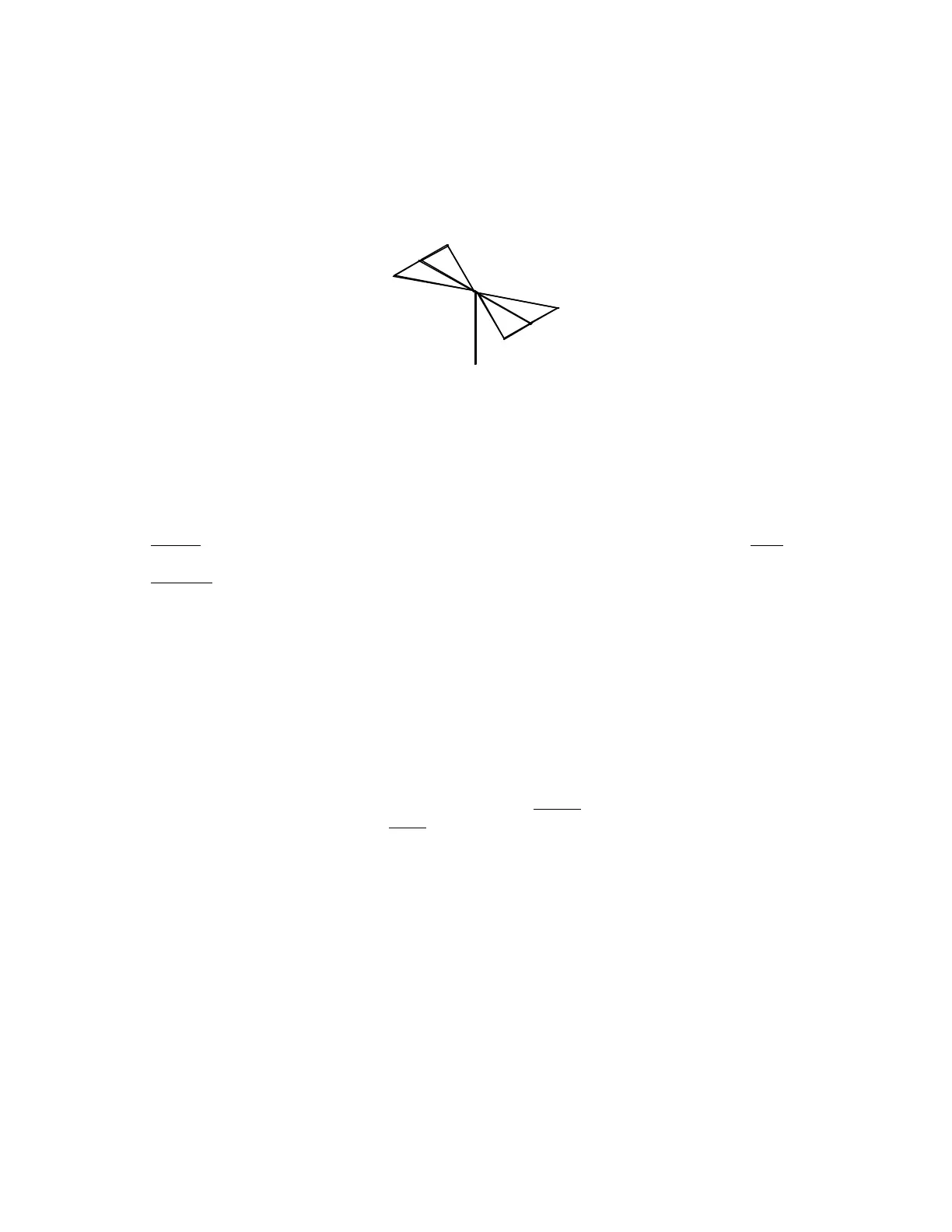
PRELIMINARY TUNING - DRIVEN ELEMENT
As always, the antenna should be clear of wires and other conductors to which it might become coupled.
1. Begin with the initial dimensions shown in the pictorial diagram. After these adjustments are
complete, set the reflector element aside and out of the way.
2.
Position the driven element as shown below so that the plane of the element is approximately 7 ft
(2.1 m). above the earth and roughly parallel to it.
3. Connect an SWR bridge and a calibrated signal source (or a transmitter) to the driven element,
making sure that the chassis is GROUNDED before plugging it into the power line in order to avoid
electrical shock.
4.
Make SWR measurements over the 20 meter band and compare them to the SWR data listed
below. If your measurements, particularly the point at which your SWR is lowest, do not resemble
those listed below it will be necessary to readjust the length of stub (M) until your lowest SWR
reading occurs at or very near that shown below. To move your lowest SWR to a higher frequency
shorten stub (M) by loosening the lower clamps of the 4-way assembly and pushing the open end of
stub (M) closer to the center of the element; to move your lowest SWR point to a lower frequency
increase the length of stub (M) by moving it in the opposite direction. Tighten the clamps and check
the SWR again, repeating this adjustment until your frequency of lowest SWR is the same as shown
below.
5.
Your 20 meter adjustments should not be significantly affected by adjustments made for the other
bands, so proceed to the 15/10 meter adjustment by noting your SWR readings over the 15 meter
band and compare them to the information given below. For 15 and 10 meters the 4-way assembly,
stub and all, on the other side of the element are moved toward the element center to lower the
frequency of the lowest SWR and away from the element center to raise the frequency of the
lowest SWR. Again, try to make your frequency of lowest SWR, coincide with that listed below.
6.
Check your 10 meter SWR. This is determined by the previous 15 meter adjustment, but it should
be reasonably close to the values given below. In any case, 10 meter tuning is quite broad, and your
frequency of lowest SWR should not differ significantly from that shown in the following chart.