-17-
FINAL ASSEMBLY
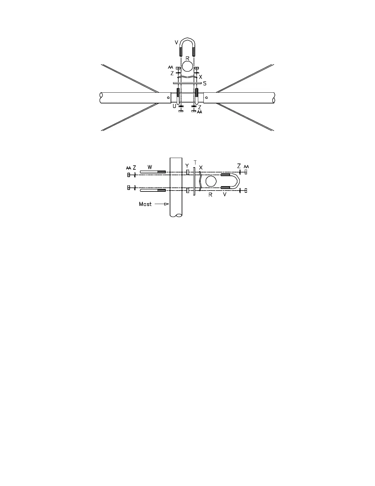
2. Install boom to mast plate (T) on boom tube (R) using two 1 1/8" U-bolt (V), two 1-1/8" backing
clamp (X), four 1/4" lock washer (Z) and four 1/4" hex nut (AA).
3. Install two 1 1/2" U-bolt (W) on the opposite side of boom to mast plate (T) using two 1 1/2"
backing clamp, four 1/4" lock washer (Z) and four 1/4" hex nut (AA). Do not tighten until the
antenna is installed on the mast (not provided).
IMPORTANT! READ THE FOLLOWING STEP THROUGH TO THE END BEFORE
PROCEEDING!
4. Install the driven element on the end of boom tube (R) using two 1 1/8" U-bolt (V), two 1-1/8"
backing clamp (X), four 1/4" lock washer (Z) and four 1/4" hex nut (AA). Position the driven
element so the SO-239 connector (O) and u-shaped stub (L) are on the RIGHT side as viewed
from the center of the antenna.
5. Install the reflector element on the other end of boom tube (R) using two 1 1/8" U-bolt (V), two
1-1/8" backing clamp (X), four 1/4" lock washer (Z) and four 1/4" hex nut (AA). Position the
reflector element so the u-shaped stub (K) is on the RIGHT side as viewed from the center of the
antenna.
This completes the final assembly. Both elements should be on the boom, with the boom to mast plate (T)
mounted in the center. The edges of the boom to element plates (S) should be within 1/4" of the plastic
end caps on boom tube (R). The spreader tubes (C) and boom to mast plate (T) should be aligned 90° to
the ground.