BW Broadcast technical manual
Page 11
Introduction
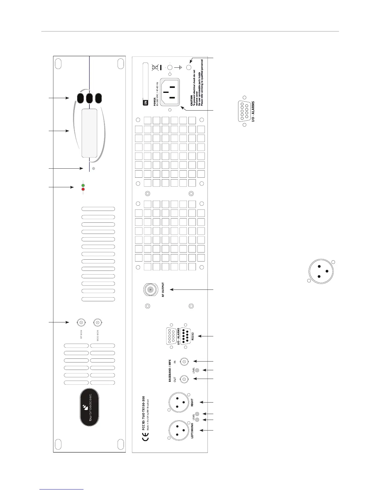
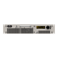
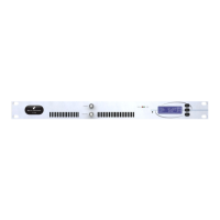
1.4 FRONT AND REAR PANELS
1. Left audio input
2. Left Input gain
3. Right input gain
4. Right audio input
5. MPX output
6. MPX level control
7. MPX Input
8. I/O + Alarms
9. RS232
10. R.F. output
11. Power socket
12. Chassis ground post
13. RF monitor output -50dBc (not suitable for
harmonic measurements)
I/O - Alarms D-type connector pinout:
Pin 1 +18V DC 200mA
Pin 2 RF Mute
Pin 3 RF failure alarm (TTL)
Pin 4 PLL failure alarm (TTL)
Pin 5 MOD failure alarm (TTL
Pin 6 GND
Pin 7 RF failure alarm (OC)
Pin 8 PLL failure alarm (OC)
Pin 9 MOD failure alarm (OC)
XLR Audio input connectors
17
18
121 2 3 4 5 6 7 8, 9 10 11
13, 14
15 16
14. Modulation monitor output (buffered multiplex,
nominally 3V peak-to-peak for 75kHz)
15. VSWR and temperature fault LEDs
16. Maximum forward power adjust
17. LCD display
18. Up / Down frequency buttons
PIN1 GND
PIN2 Hot (+)
PIN3 Cold (-)