BW Broadcast technical manual
Page 12
Introduction
1.5 CONTROL AND MONITOR LCD
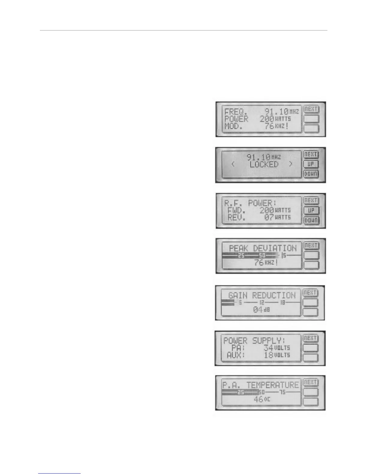
The front panel LCD graphics display has seven screens (shown below). These allow monitoring of the transmit-
ter’s R.F., audio and other parameters and the adjustment (if internally allowed) of the transmitter’s power and fre-
quency. You can move through the screens by pressing the NEXT button, which will display them in the following
order.
Main parameter screen.
This shows together the three most important transmitter
parameters. Frequency, R.F. output power and the peak
deviation.
Frequency display and control
This screen will display the frequency and PLL locked condi-
tion. The up and down buttons will allow 100 kHz frequency
steps from 87.5 to 108Mhz if the internal switches are set
to 4440. If the frequency is set internally with the rotary
switches then the up / down buttons will give a ‘not allowed’
message
R.F. power
The forward and reverse R.F. powers are displayed. The
up/down buttons will allow power control if internally allowed.
The maximum output power is governed by the maximum
power set adjustment (see R.F. pwr control section). If the
frequency is set internally with the rotary switches then the
up / down buttons will give a ‘not allowed’ message
Peak deviation
This display indicates the peak and average deviation. Peak
deviation is shown both numerically and as a moving single
pixel wide bar. Average deviation is shown with the solid
black bar. Over-deviation will display an exclamation ( ! )
Gain reduction
This display indicates the amount of gain reduction of the
internal audio limiter. The range is 0 to 24 decibels of gain
reduction.
Power supply
Power amplifier voltage is shown together with the transmit-
ters secondary supply that feeds the exciter section. The
power amplifier voltage will vary depending on set output
power and the presence of any fault conditions which also
cut the voltage back and with it the R.F. output.
P.A. temperature
This display indicates the temperature of the heatsink that
the R.F. power transistor is bolted to. The normal operating
temperature range is 40-60 degrees at full R.F. power out-
put.