EN
9
Ozone-water mixture (optional)
The ozone-water mixing device is an important part of the ozonation
process. The mixing device draws the ozonic gas from the unit and
mixes the ozone with the water. The BWT mixing device guarantees
optimalecacy(mixingeect)withminimumuseofenergy.Theozone
is dissolved in the water, resulting in rapid and safe reaction of the ozone
with the water contaminants.
4.3 Function monitoring
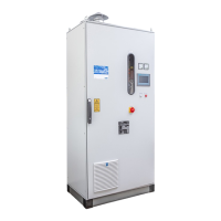
The ozone device is controlled and monitored by a programmable logic
controller (PLC). The operator can use the TP (touch panel) to intervene
in the program sequence and set the operating condition required.
The TP display shows all operating condition messages, operating values
and fault messages as plain text in the 9 languages available: German,
English, French, Italian, Spanish, Polish, Russian, Chinese, Indonesian.
– The current ozone output
– The remaining capacity or the remaining running time of the dryer
while in operation
– The remaining regeneration time of the dryer being regenerated
4.4 Power failure
The PLC permanently stores all operating parameters in the event of
a power failure.
Caution: After a prolonged power failure or if the power supply has been
disconnected for a long time, the remaining capacity of both dryers is
set to zero after about 24 days. When power returns, both dryers are
automatically regenerated in succession. The unit starts generating
ozoneonlyaftertherstdryerisregenerated.
If the power returns before 24 days pass, the unit continues operation
in the same operating condition it was in prior to the power failure.
Exception: Fault messages are deleted when the unit restarts after a
power failure.
4.5 Control connections
Youcanndanoverviewoftheunit'scontrolconnectionsintheelectri-
cal circuit diagram on sheet “H”. The connections perform the following
function:
Remote ozone on
Theozonedevicecan beswitchedonandofrom aremotecontrol
point via this contact if the operating mode for “switch on ozone” on the
unit is set to “ext. contact” and the operator has enabled the local ozone
generation release for the unit. Ozone is generated in accordance with
the pre- and post-operation purge durations.
Post-operation purge
Whenthesystemisshuto,ozonegenerationisshutoandthepost-
operation purge is triggered. In order to carry out the post-operation
purge, the same hydraulic conditions as are required for ozone operation
must be maintained until the post-operation purge is completed. This me-
ans that all required pumps, such as circulation pumps, must continue to
run during the post-operation purge. The ozone device itself makes sure
that the booster pump operates correctly (see “Booster pump enabled”).
The post-operation purge can be cancelled from the control point by
switchingotheacknowledgementsignalfromtheboosterpumpduring
the post-operation purge. This facilitates setting the actual post-purge
duration via the control point. Post-operation purges of varying duration
can be implemented in this way. The duration set on the TP must be
at least as long as the longest post-operation purge. The system can
also be switched o immediately without a post-operation purge by
simultaneouslyswitchingo thecontactsofthe“Remote OzoneOn”
and “Booster pump acknowledgement” inputs.
Booster pump enabled
When ozone generation is enabled, the unit starts the integrated booster
pumptobuilduptheairowusingthiscontact.Asanoption,thebooster
pump power switch and acknowledgement signal can be integrated into
the ozone device as a special order.
The booster pump must have direct acting control, that is, without
interference from other external control signals. Non-observance can
result in serious damage to the device (see the circuit diagram, sheet H).
Booster pump acknowledgement
This contact sends an acknowledgement signal to the ozone device to
conrmthattheboosterpumpofthecircuitinquestionison.Theboos-
ter pump is switched on when ozone generation is enabled. When the
booster pump acknowledgement signal is received, the power supply
ofthehighvoltagetransformerandthecoolingwaterowfortheozone
tubes are activated.
Whenswitchingoozonegeneration,itisstillpossibletodeterminethe
post-operation purge duration from the control point using this contact;
see Post-operation purge.
Regeneration blower operation
The adsorbed moisture is expelled from the dryer while the regeneration
blower is operating. The reg. blower operation dry contact can be used
to increase room ventilation in this period.
Flow monitor for cooling water
For monitoringan existingcooling water ow,this contactgives you
theoptionofconnectingthelimitcontactofanexternalowmeter.To
do so, the “Monitoring cooling water” operating mode has to be set to
“Thermostat+min.contactowmeter”.
4.6 External safety monitoring
Fault/fault free
The operating condition (operation/fault) of the unit can be monitored
remotely via a dry group fault message contact (CIC). The contact is
closed when no faults are pending. In the case of units with data bus (Pro-
net/Probusoption),eachindividualfaultmessageisalsotransmitted.
Gas detector
An ozone gas detector must be installed in all rooms subject to possible
emission of ozone. The sensor must be mounted at a height of approx.
50 cm above the oor. If ozone escapes, the device responds and
switchesoozonegeneration.
Emergency stop
An emergency stop button must be mounted near every entrance to the
installation location, to allow ozone generation to be deactivated in an
emergency. When you press the emergency stop switch, the high voltage
supplyandthereforetheozonegenerationareswitchedoimmediately.
However, the mains voltage is not disconnected.
Door safety switch
In the ozone cabinet, a door safety switch is installed for each cabinet
door. When you open the door, the door safety switch switches the high
voltagesupplyandthereforetheozonegenerationoimmediately.

 Loading...