EN
33
s¬Generally, we recommend the operation with softened feed
water to achieve an extending of the life and reliability of the
RO membranes.
D
All hoses have been connected and are watertight.
When installing the optional “high-efficiency“ WCF -
Kit, the enclosed operation manual must be observed!
s¬0LEASE¬OPEN¬THE¬VALVE¬FOR¬THE¬FEED¬WATER¬SUPPLY
s¬#ONNECT¬THE¬2/¬UNIT¬TO¬THE¬POWER¬SUPPLY¬6¬(Z
DThe functions of the control unit and software configuration
are described in Part 3.1 - 3.8.
s¬7E¬RECOMMEND¬THAT¬THE¬PUMP¬PRESSURE¬IN¬EACH¬OPERATING¬
mode to set at approx. 8.1bar!
s¬)NSTRUCTIONS¬FOR¬THE¬7#&¬KIT¬INSTALLATION¬AVAILABLE¬IN¬Part 5.3.
s¬Note: Discard the first produced permeate during the first
10 minutes after any new installation/first commissioning or
at any membrane replacement.
Note: Please run the RO unit a few days to reach the
full performance (WCF and permeate quality).
Note: A drop of temperature by 1°C will reduce the
permeate output of the membranes by approx. 3.0%.
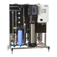
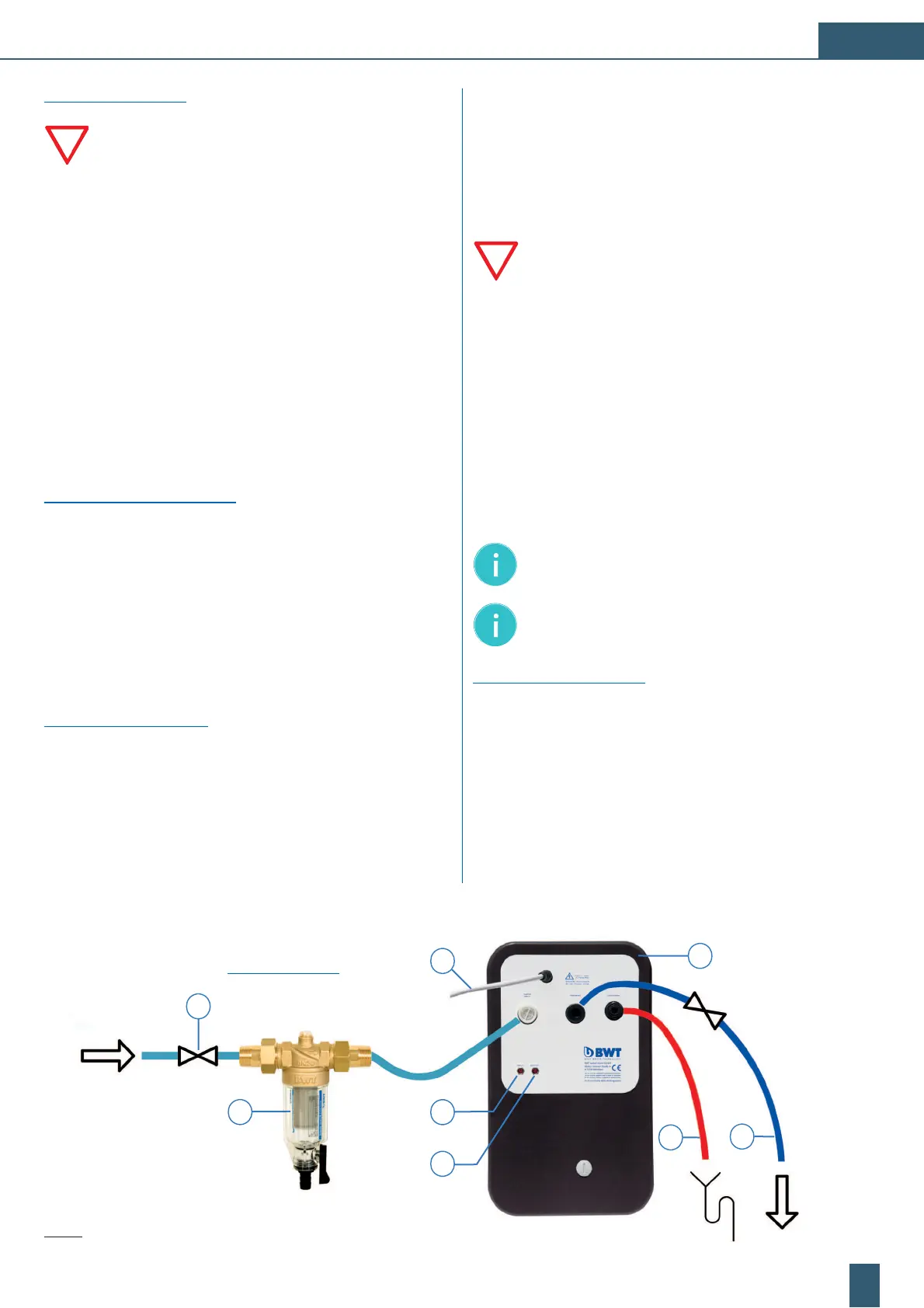
Possible installation layout:
1
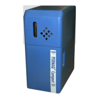
BWT PERMAQ
®
compact 2 - 6 reverse osmosis
2 External pre-filter (not included in the delivery)
3 Permeate outlet ready for the connection to the consumer/tank
4 Stop valve for feed water and permeate hose
5 Mains plug, cable length 1.8m
6 Concentrate outlet
7 Optionally: External contacts (INPUT), start/stop
8 Optionally: External contacts (OUTPUT), alarm output
Hydraulic installation:
Please respect the general installation instructions for the
preparation of water installations as well as the general
hygiene requirements.
s¬0LEASE¬READOBSERVE¬ALL¬APPLICABLE¬SPECIlCATIONS¬OPERATING¬
and safety instructions prior to the installation.
s¬0LEASE¬USE¬ONLY¬APPROVED¬mEXIBLE¬HOSES¬ACCORDING¬TO¬
the DVGW W 543 requirements.
s
Please adhere to all dimensions as well as bending radius in
the assembly of the flexible tubes and connection sets.
s¬4HE¬"74¬0%2-!1
®
compact 2 - 6 device line is to be installed
and operated vertically.
s¬4HE¬UNIT¬MAY¬NOT¬BE¬CONNECTED¬TO¬THE¬WATER¬MAINS¬BY¬RIGID¬PIPES
s¬!¬HYDROPHORE¬OR¬A¬STORAGE¬TANK¬WITH¬A¬BOOSTER¬PUMP¬COULD¬
be installed in the permeate line between the RO unit and the
consumer, if depending on the application a short-term peak
flow is required.
Connection to the water pipe:
s¬4HE¬DEVICE¬HOSES¬MUST¬BE¬INSTALLED¬IN¬A¬mEXIBLE¬MANNER¬
(without an
y tension) to maintain a safe operation.
s¬#HECK¬ALL¬WATER¬CONNECTIONS¬TO¬ENSURE¬THAT¬THEY¬ARE¬TIGHT¬AND¬
waterproof.
s¬'UIDE¬THE¬mEXIBLE¬CONCENTRATE¬HOSE¬WITH “free flow“ condition
to the on-side connection of the drain pipe (with a slope of 1%)
and fasten it. The “flexible“ hoses must not have any bends or
cross-sectional constrictions. Observe during the installation that
the concentrate- and permeate hoses were correctly connected.
Notes for initial operation:
s¬#ONNECT¬THE¬2/¬UNIT¬WITH¬THE¬ELECTRICAL¬POWER¬SUPPLY¬
(230V, 50Hz). The wall socket has to be earthed.
s¬0LEASE¬CONSIDER¬THE¬INDIVIDUAL¬MANUAL¬OF¬THE¬external pre-filter.
s¬4HE¬water hardness can vary in different areas.
3
6
1
4
Fig. 3: Installation scheme / example
2
'ZVGTPCNRTGƂNVGT
BWT Protector Mini C/R 1/2“ ;
BWT accessories
5
7
8
 Loading...