BYAN SYSTEMS, INC.
Automated Gate and Access Control Products
413 Linden • Lusk, WY 82225 • (800) 223-2926
5
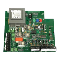
Accessory Hook-Ups*:
There are many accessories available that are compatible with the G2M that will give the end
user different options for safety, security, and system operations. Since it would be impossible to
outline all possible combinations, we will simply outline a few of the most common. Keep in
mind; these instructions are specific to the brand and model most commonly used by Byan
Systems. Your accessories may differ from the ones listed below. Always consult the
Installation Instructions included with an accessory before connection it to any operating system.
Linear GRD_1 Radio Receiver:
1. Separate the four wires coming out of the bottom of the receiver (1 Red, 1 Black, & 2
Gray).
2. Connect the black wire to terminal 3 of the accessory terminal strip.
3. Connect the red wire to terminal 4 of the accessory terminal strip.
4. Connect one of the gray wires to terminal 16 of the accessory terminal strip.
5. Connect the other gray wire to terminal 18 of the accessory terminal strip for open only
or terminal 19 for use as a reversing device.
6. If an external antenna is required, locate the bulk head connector supplied with the
receiver.
7. Drill 1 3/8” hole in the enclosure where you would like to mount the antenna.
8. Install the bulk head connector in the hole using the hardware included with the receiver.
Be sure to use thread locking compound in the threads when installing the connector.
9. Connect the supplied coax between the receiver and the bulk head connector and attach
the antenna to the outside of the connector.
Mag-Lock Relay Using Idec SH2B-05 Base w/RH2B-UDC12V Relay:
1. Connect terminal 14 on the relay base to terminal 6 of the accessory terminal strip.
2. Connect terminal 13 on the relay base to terminal 5 of the accessory terminal strip.
3. Connect Neutral or Ground from the mag-lock transformer directly to the mag-lock.
4. Connect Hot from the mag-lock transformer to terminal 9 of the relay base.
5. Connect terminal 1 on the relay base to the mag-lock.
6.
Loop Detector Using Idec SR3P-06 Base w/EDI LMA1100-120 Loop Detector:
1. Connect terminals 7 & 8 to the in ground loop leads.
2. Connect 120V AC Neutral to terminal 2 of the detector base.
3. Connect 120V AC Hot to terminal 1 of the detector base.
4. Connect desired signal wires from the detector base to the accessory terminal strip of the
G2M.
Shadow: (instruction referencing relay refer to Idec SH2B-05 relay base and RH2B-UAC110-
120 relay)
1. Connect terminal 9 of the relay base to terminal 5 of the detector base.
2. Connect terminal 5 of the detector base to terminal 9 of the accessory terminal strip.
 Loading...