BYAN SYSTEMS, INC.
Automated Gate and Access Control Products
413 Linden • Lusk, WY 82225 • (800) 223-2926
6
3. Connect terminal 5 of the relay base to terminal 10 of the detector base.
4. Connect terminal 10 of the detector base to terminal 10 of the accessory terminal strip.
Safety:
1. Connect terminal 5 of the detector base to terminal 9 of the accessory terminal strip.
2. Connect terminal 10 on the detector base to terminal 10 of the accessory terminal strip.
Free Exit:
1. Connect terminal 5 on the detector base to terminal 16 of the accessory terminal strip.
2. Connect terminal 6 of the detector base to terminal 18 of the accessory terminal strip.
*See conversion tables on pg. 7 for corresponding terminal blacks in the Byan Prewires.
Characteristics:
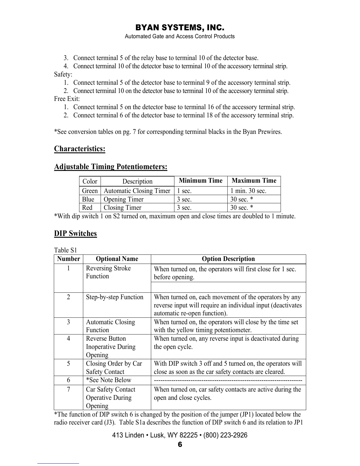
Adjustable Timing Potentiometers:
*With dip switch 1 on S2 turned on, maximum open and close times are doubled to 1 minute.
DIP Switches
Table S1
Number Optional Name Option Description
1 Reversing Stroke
Function
When turned on, the operators will first close for 1 sec.
before opening.
2 Step-by-step Function When turned on, each movement of the operators by any
reverse input will require an individual input (deactivates
automatic re-open function).
3 Automatic Closing
Function
When turned on, the operators will close by the time set
with the yellow timing potentiometer.
4 Reverse Button
Inoperative During
Opening
When turned on, any reverse input is deactivated during
the open cycle.
5 Closing Order by Car
Safety Contact
With DIP switch 3 off and 5 turned on, the operators will
close as soon as the car safety contacts are cleared.
6 *See Note Below ---------------------------------------------------------------------
7 Car Safety Contact
Operative During
Opening
When turned on, car safety contacts are active during the
open and close cycles.
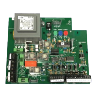
*The function of DIP switch 6 is changed by the position of the jumper (JP1) located below the
radio receiver card (J3). Table S1a describes the function of DIP switch 6 and its relation to JP1
Color Description
Minimum Time Maximum Time
Green Automatic Closing Timer 1 sec. 1 min. 30 sec.
Blue Opening Timer 3 sec. 30 sec. *
Red Closing Timer 3 sec. 30 sec. *
 Loading...