EasyManua.ls Logo

Byan System G2M User Manual

Byan System G2M
16 pages
To Next Page IconTo Next Page
Page #1 background imageLoading...
Page #1 background image
BYAN SYSTEM, INC.
413 LINDEN
LUSK, WY 82225
(800) 223-2926
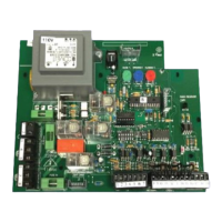
G2M Control Board
Installation and Operations Manual
Specifications
Power supply Single Phase 115V or 220V 50/60 Hz AC
Motor Power Consumption Up to 550W or 3/4 hp
Electric Lock Output 12V DC 1A max.
Accessory Power Output 24V AC 1A max.
Input Power Fuse 2A, 250V; 5mm x 20mm tubular glass
Motor Power Fuses 6A, 250V; 5mm x 20mm tubular glass
P.O. BOX 1384 FAX (307) 334-2028

Questions and Answers:

Byan System G2M Specifications

General IconGeneral
BrandByan System
ModelG2M
CategoryController
LanguageEnglish

Summary

G2M Control Board Overview

Specifications

Technical specifications of the G2M control board, including power, motor, and output details.

G2M Control Board Layout and Terminals

Board Layout Diagram

Visual representation of component placement on the G2M control board.

Terminal Strips

Explanation of the power/motor and accessory terminal strips.

Power and Motor Run Terminals

Commercial Power Hook-Up

Detailed instructions for connecting commercial power to the board's terminal strip.

Accessory Terminal Connections

Accessory Terminal Table and Uses

A table listing accessory terminals and their possible uses.

Accessory Hook-Up Procedures

Common Accessory Connections

Instructions for connecting common accessories like radio receivers and relays.

Configuration and Settings

Adjustable Timers and DIP Switches

Details on timing potentiometers and DIP switch functions for board configuration.

DIP Switch Options and Prewire Conversions

DIP Switch S1a and S2 Functions

Explanation of specific DIP switch behaviors and options.

G2M to Byan Prewire Terminal Conversion

Tables converting G2M terminals to Byan prewire systems.

Prewire Terminal Conversion Tables

Power/Motor and Accessory Conversions

Conversion tables for power, motor, and accessory terminals to various prewire layouts.

Accessory Prewire Conversion Tables

Accessory Terminal to 24x20 and 30x24 Prewire

Conversion tables for accessory terminals to 24x20 and 30x24 prewire layouts.

Prewire Layout Diagrams

12x10 and 20x16 Wiring Layouts

Wiring diagrams for 12x10 and 20x16 prewire configurations.

24x20 Prewire Layout Diagram

24x20 Wiring Layout Breakdown

Wiring diagram breakdown for the 24x20 prewire layout, including exit/entry.

Troubleshooting Guide

Common Symptoms and Solutions

Lists common operational symptoms, their causes, and recommended solutions.

T2M Leaf Delay Card

Card Description, Timers, and Installation

Overview of the card, its timers, and installation procedure.

T2M Leaf Delay Card Adjustment

Adjustment Procedure

Step-by-step instructions for adjusting the open and close delay timers.

Product Warranty Information

Four-Year Limited Warranty Terms

Details the terms, conditions, and limitations of the product's four-year warranty.