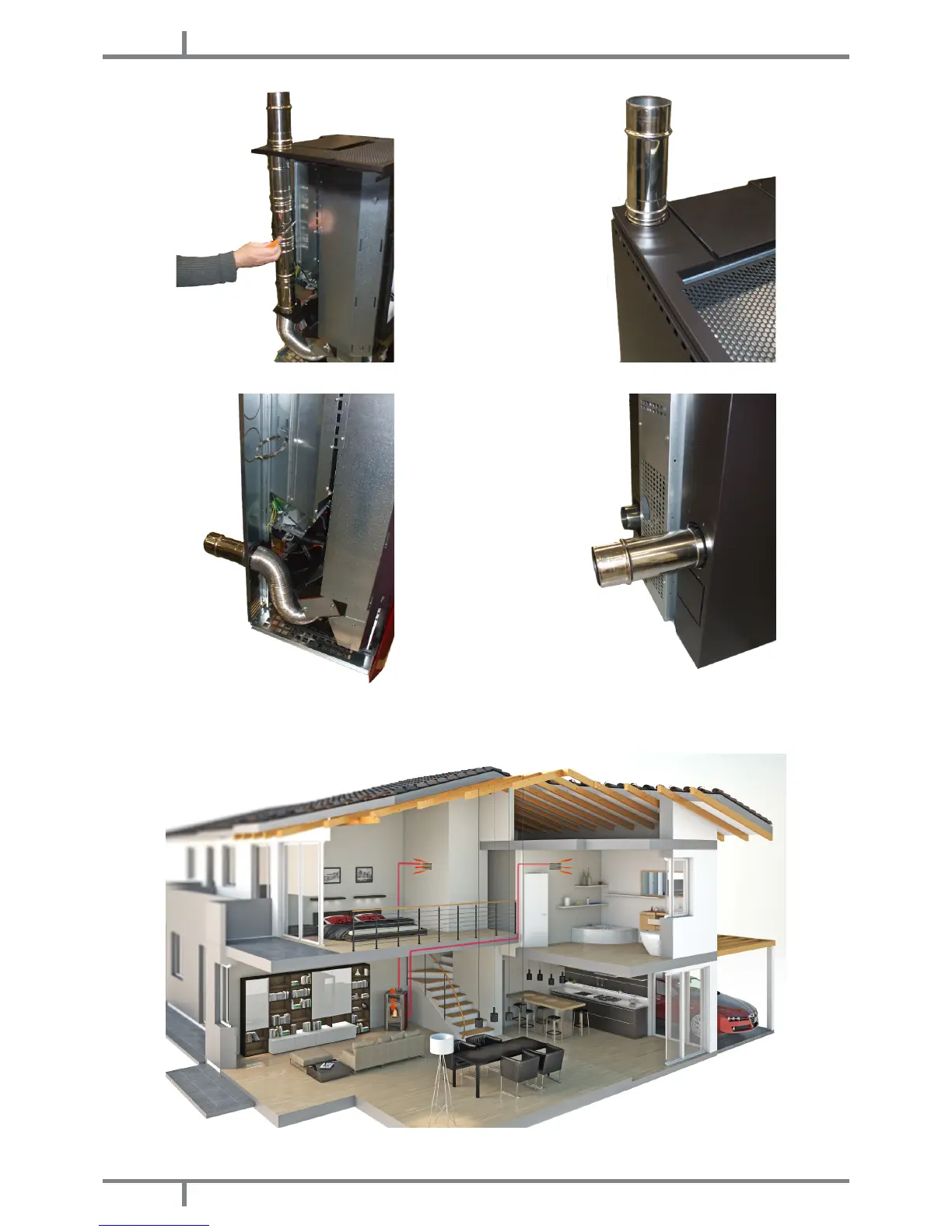
Fig. 40 - Upper pipe position Fig. 41 - Upper hot air outlet
Fig. 42 - Back pipe position Fig. 43 - Back hot air outlet
• The hot air can be forced in ducts in the upper part (see Fig. 40 page 24 and Fig. 41 page 24).
• Or make the air exit from the rear (see Fig. 42 page 24 and Fig. 43 page 24).
Fig. 44 - Ducting system example
• If the stove is not tted with ducting system, it provide a hot air capacity ranging from a minimum of 61 m
3
/h
 Loading...