5
LEGIOMIX
2.0
Series 6000
T
AMB.
0÷50°C
L - N: 230 V
˜
6,5 VA
IP 54
CS 176
CS 180
CS 179 (OPZ)
L N
NO C NC NO C NO C
CS 176
μ
5(2) A 250 V
˜
230 V
˜
50 Hz
ALARM
OUT
1
OUT
3
OUT
2
RETURN
PROBE
MIXED
PROBE
T2
RS485
BA
IN 2 T1IN 1
CS 180
CS 179 (OPZ)
Cale S.p.A.
S.R. 229 n° 25
28010 Fontaneto d’Agogna
Italy
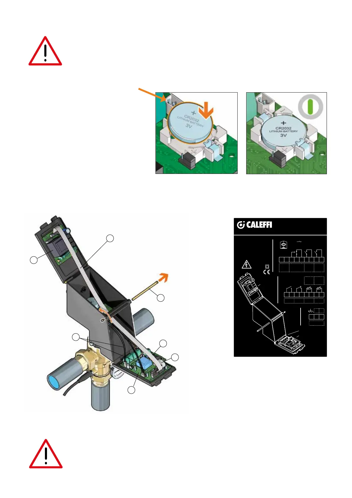
Wiring diagrams
IMPORTANT:
Risk of electric shock. The CS176 board is live. Cut off the electric supply before carrying out any work. Failure in following these
instructions may result in injury of persons or damage to property. In case of power failure the system can activate an alarm
through OUT1 relay. Date and time are maintained by the battery. If the battery is low, the system displays the "BATTERY LOW"
alarm.
1
6
3
2
4
5
7
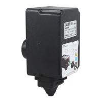
Regulator-actuator
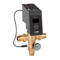
Battery installation
Before connecting the power supply, insert the battery supplied, type CR 2032. The presence of the battery
allows the clock continuous updating. In case of low or missing battery, if there is no network, the device does not
ensure that the time and date are stored and therefore that the programmed disinfections are executed correctly.
1 Actuator-regulator opening/closing pin
2 Power supply board (CS176)
3 Control board (CS180)
4 Multi-pole cable for board connection*
5 Motor connection cables*
6 RS-485 Interface board (CS179) (OPTIONAL)
7 RS-485 Interface connection cable (OPTIONAL)
* already assembled in factory
4
Optional battery connector
code F0000692
NOTE: It is possible to replace the button battery with
an optional battery code F0000692, type ER AA
Lithium-Chloride of thionyl 3,6 V, to be connected
to the connector on the board.
The battery life is approx. 10 years.
For connecting the optional battery, its installation
and specifications, see the instruction sheet
H0003948.
 Loading...