7
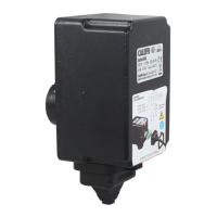
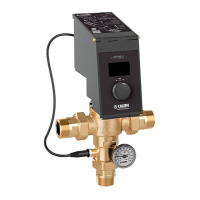
Front panel
1 LCD display
2 Control knob
3 Green LED: - On (network presence)
4 Red LED: - Fixed (disinfection or thermal shock in progress, full
scale acquisition)
- Flashing (alarm condition)
Indication on LCD display
On the front of the device there is a backlit alphanumeric LCD
display for parameter setting, interventions programming, working
statuses and alarms display.
Navigating through appropriate menus, using the control knob
only, it is possible to configure the device and set the various
parameters.
Operating status
Depending on the times and the programs that have been set, the device
may be in one of the following operating modes:
• Regulation
• Disinfection
• Thermal shock*
• Zero and full scale acquisition
*(this function has priority over the disinfection/regulation).
In the event of anomalies, the device manages and signals an alarm trying
to set into a safety condition for the user. The device is equipped with a
non-rechargeable battery that keeps the clock working in the event of
electric supply failure.
Regulation
The electronics must adjust the flow temperature through the actuator in
order to reach the working set-point. The electronic actuator adjusts the
flow so as to have a temperature centered in a suitable working range,
within which the fine and dynamic adjustment is made by the thermostat.
The mixing temperature is set through the interface. The management
system always checks in real time the flow temperature detected by
the probe: if the flow temperature deviates excessively from the set
value, a correction is made through the electric motor. In the case of
installation with a return probe present, it is not used for the water mixing
temperature adjustment.
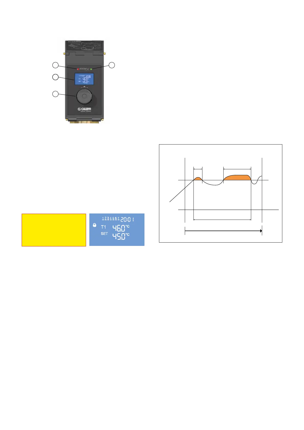
Disinfection
In this mode, the device performs thermal disinfection, which consists in
raising the mixed water temperature for a defined period of time.
The following can be set:
- Days of the week for performing the disinfection
- Minimum disinfection temperature
- Disinfection start time
- Minimum stay time above the minimum disinfection temperature in
order to evaluate the successful outcome of the disinfection
- Maximum time within which it is possible to perform the disinfection
The disinfection can be:
- Programmed: it starts in the days and hours set
- Activated through the control: it can be controlled by the device from
the "Controls submenu" or remotely through optional board
- Activated by IN1 inlet
The disinfection in progress OUT3 relay and the recirculation pump
management OUT2 relay are always activated during the disinfection.
If the disinfection temperature does not last for sufficient time and the
maximum available time is exceeded, the disinfection will be considered
as failed by signalling the relevant alarm.
8
Thermal shock
In this mode, the device raises the flow temperature to the set value for
a certain period of time. The disinfection in progress OUT3 relay and the
recirculation pump management OUT2 relay are always activated during
the thermal shock.
Zero and full scale acquisition
In the zero acquisition mode, the device totally closes the adjusting screw
to check the correct phasing between the motor and the valve. In full
scale acquisition mode, the device fully opens the adjusting screw so
it can check all the stroke (potentially hazardous condition indicate with
fixed red LED). The zero and full scale acquisition controls are activated
during the installation or after the "Reset alarms” control.
Additionally, the zero acquisition mode is activated whenever an electric
supply failure occurs for at least 60 minutes and at the outlet from any
disinfection/thermal shock. It is recommended to perform the full scale
acquisition with shut-off valves closed at the mixing valves inlets.
Reset
In the menu there is a special control to reset to the initial conditions. The
history is not reset.
Test
The device performs full strokes in order to check that there are no
obstructions during the motor opening and closing strokes. The display
shows the encoder steps and the power consumption (mA). It is possible
to interrupt the test function at any time pressing the control knob.
t
1
t
2
Σ t
s
> minimum disinfection time
minimum
disinfection
temperature
CHECK ON DISINFECTION
Temperature [°C]
Time [s]
Disinfection start
Disinfection end
maximum disinfection time
4
1
2
3
For management and programming
of the device refer to the
"Programming Manual"
code H0003581
 Loading...