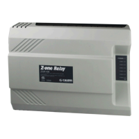
6
BOARD TERMINAL CABLE TYPE
UNSHEATHING
IN mm (L) POS. A *
UNSHEATHING
IN mm (L) POS. B *
CS176
L/N 2 X 0,75 (H05VV-F) 250 140
OUT1 3 X 1 250 140
OUT2 2 X 1 250 140
OUT3 2 X 1 250 140
CS180
T2 2 X 0,75 140 250
T1 2 X 0,75 140 250
IN1 2 X 0,75 140 250
IN2 2 X 0,75 140 250
CS179 RS-485 2 X 1 TW+SCH 190 300
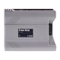
Cables wiring and positioning
The passage of the connecting cables must be prepared trying to
separate the electric supply cables from the signal cables using the
appropriate clamps. This image shows an example of a possible
cable layout and their passage through the cable seals and cable
glands included in the supply. For different cases use special
insulating sheaths.
* NOTE: for installation, see page 9.
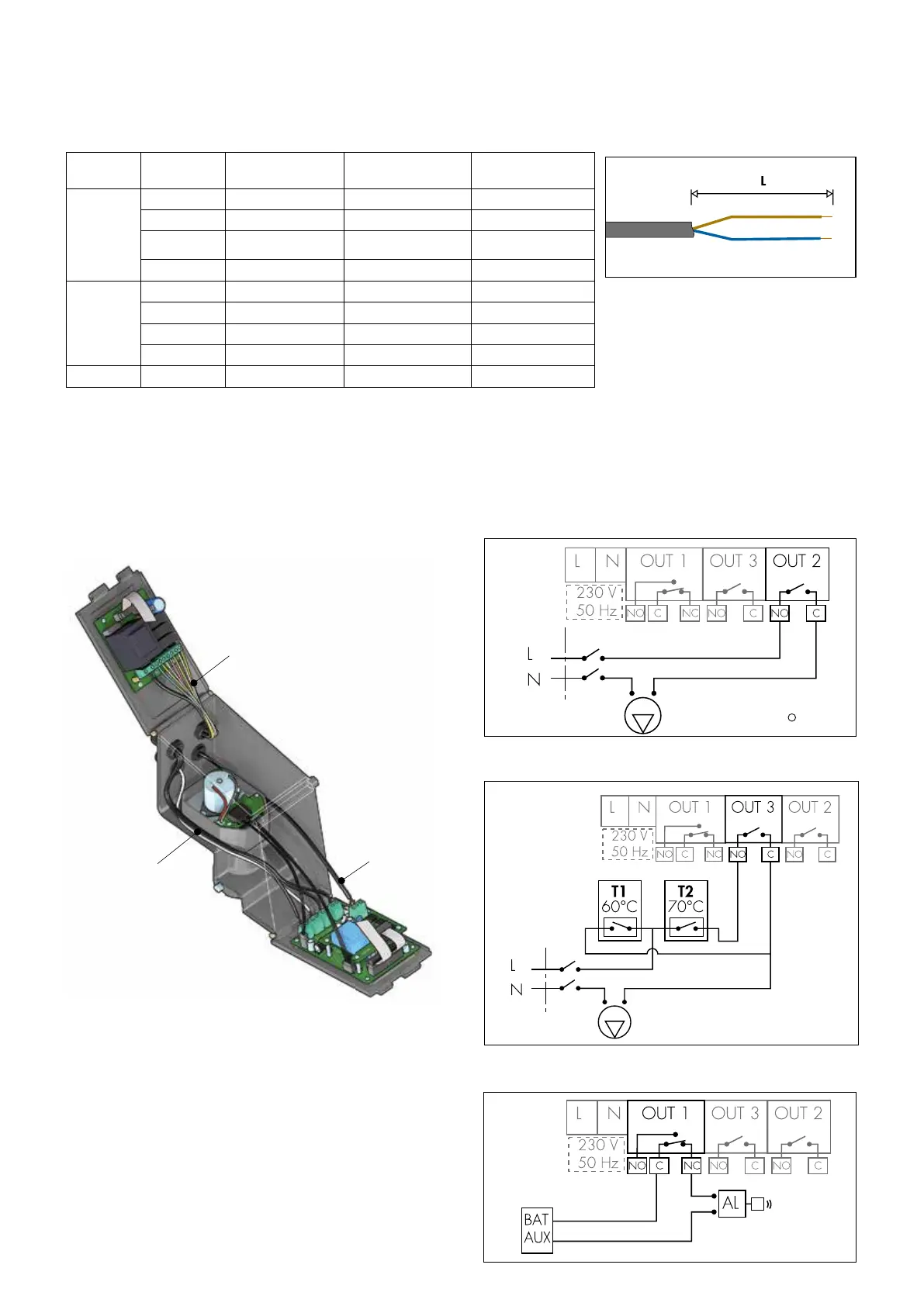
Here following the wiring diagram of the OUT 3 relay for connection to
the second storage thermostat.
Recirculation pump
Relay contact for recirculation pump and second storage
thermostat and alarm management
Here following the wiring diagram of the OUT 2 relay for managing the
recirculation pump. The device incorporates a digital clock used to
manage a recirculating pump according to pre-set time slots.
Here following the wiring diagram of the OUT 1 relay for alarm
management.
Storage primary pump
Recirculation pump
Storage primary pump
Connections layout: connections must not create thrust stresses
on the circuit board.
Cables pathway
Mimimum dimensional characteristics to respect for board electric connections: connection cable cross sections and lengths.
Observe the applicable regulations in force in the country of installation.
Electric supply cords
and relays
Signal and probes
cables
RS-485

 Loading...