Plumbing installation
Before installing the Caleffi mixing valve, the pipes must be flushed to prevent impurities in the water from affecting performance. The following are
indicated on the body of the mixing valve:
- H hot water inlet
- C cold water inlet
- MIX mixed water outlet
In systems with mixing valves, check valves must be installed to prevent undesired backflow.
We recommend always installing strainers of sufficient capacity at the inlet of the water mains and shut-off valves forany maintenance operations.
The mixing valves must be installed according to the installation diagrams in this manual; they an be installed either vertically or horizontally, with
actuator not overturned. To facilitate the display reading and setting, it is possible to change the position of the motor related to the valve in four
positions at 90°, there is also the possibility to reverse the two panels.
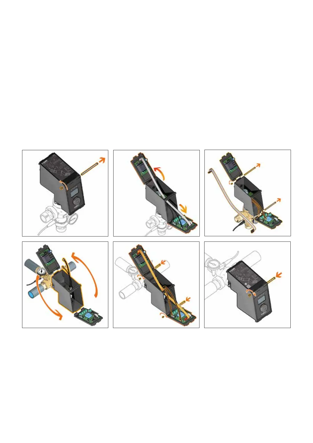
In order to reverse the panels, before to electrically wire the device, it is necessary to carry out the following operations:
1 - Remove the opening/closing pin (POS. A: factory setting).
2 - Open the panels.
3 - Disconnect the board connectors, motor connector, and remove the pins.
4 - Remove and reverse the panels.
5 - Reconnect the boards connector and the motor connector, insert the pins.
6 - Close the panels and insert the opening/closing pin (POS. B).
Commissioning
Due to the special purposes for which the electronic mixing valve will be used, it must be commissioned in accordance with current regulations and by
qualified personnel using suitable measuring instruments. Check that the hot and cold water supply pressures are within the operating limits of the mixing
valve. Check the temperature of the hot water from the storage, T ≥ 60°C.
In the installation log book, record all the parameter settings made and the measurements taken.
9
1 2 3
4 5 6
8
POS. A
POS. B
Max 1 N•m
 Loading...