7
8
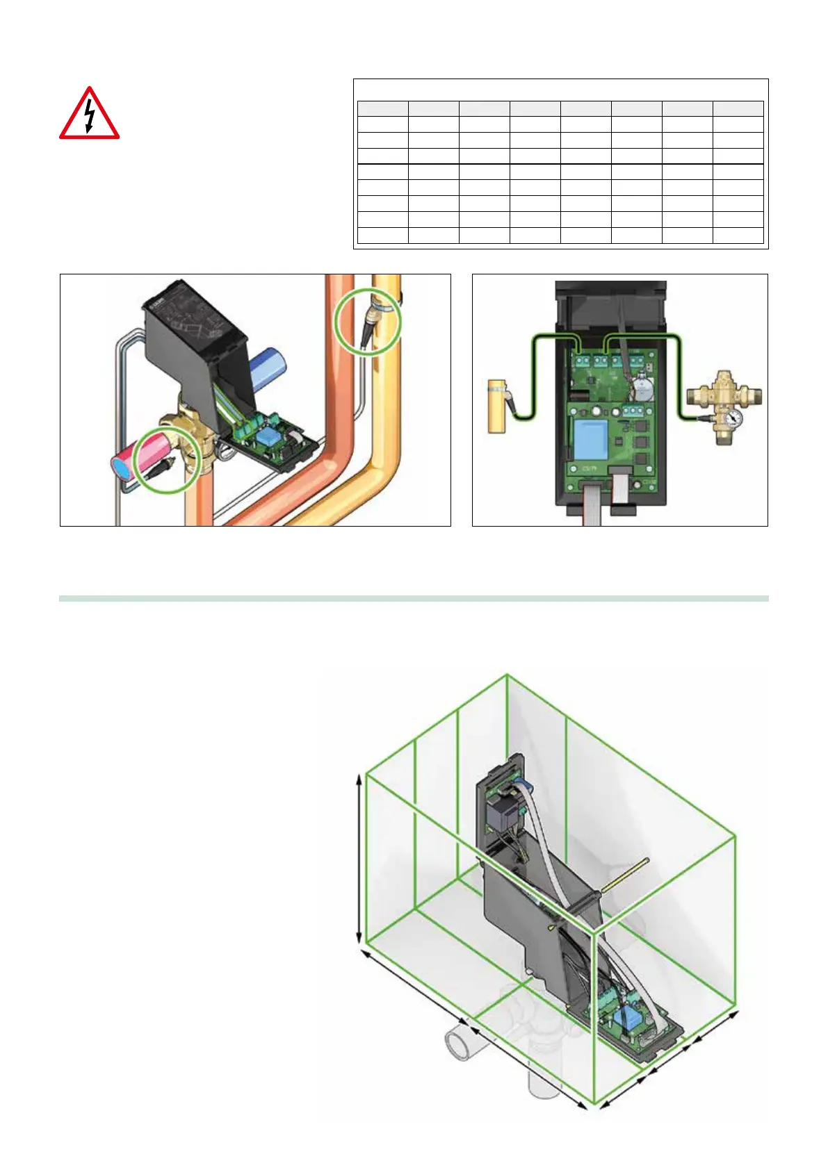
Connection of probes:
If necessary for the installation,
the cable connecting the flow and
return probes with the controller
must be installed in a raceway. If the
connection cable shares the raceway
with other power cables, an earthed
shielded cable must be used.
°C
-20
-15
-10
-5
0
5
10
15
Ω
97060
72940
55319
42324
32654
25396
19903
15714
°C
20
25
30
35
40
45
50
55
Ω
12493
10000
8056
6530
5327
4370
3603
2986
°C
60
65
70
75
80
85
90
95
Ω
2488
2083
1752
1480
1255
1070
915
787
°C
100
105
110
115
120
125
Ω
680
592
517
450
390
340
Probe resistance table
Recommended minimum distances
In order to ensure adequate space for proper installation and
maintenance of the device, the distances shown in the figure
must be observed.
Perform the hydraulic installation of the temperature probes and provide electrical wiring.
350
200
300
110
88
110
 Loading...