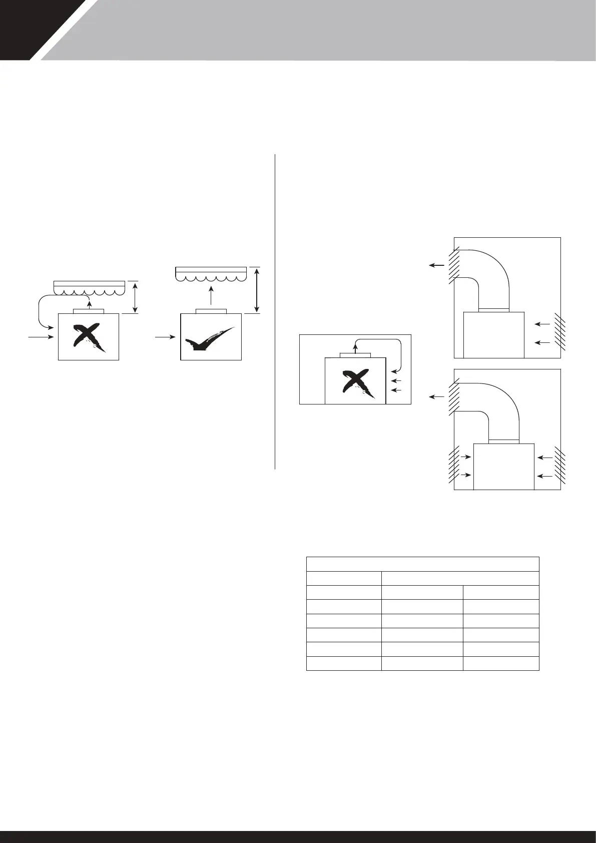
Due consideration must be given to air flow, ie do not obstruct inlet or
outlet and ensure discharge air cannot recirculate to inlet (see figures
1 and 2)
Grill or apertures MUST comply wi figures (see Table 1)
< 3 m
CANOPY OR OBSTRUCTION
TOO CLOSE
> 3 m
TYPICAL OUTSIDE INSTALLATION
FIGURE 1
FIGURE 2
TYPICAL INSIDE OR PLANT ROOM INSTALLATION
(NOT RECOMMENDED FOR LONG DUCT RUNS).
THE PLANT ROOM IS NOT TO BE USED AS AN
OCCUPIED SPACE.
ADEQUATE
DUCTING
ADEQUATE
DUCTING
PRO-PAC
90/140
PRO-PAC
30/45/70
TABLE 1
MODEL Minimum Free Area m²
Inlet Discharge
Pro-Pac 30 0.59 0.25
Pro-Pac 45 0.98 0.42
Pro-Pac 70 1.19 0.52
Pro-Pac 90 1.731 0.84
Pro-Pac 140 2.138 1.04
2. AIR FLOW
TABLE 1
Required Free Areas to provide air flow to and from heat pumps when
installed on an enclosed area or where required to pass rough a wall
etc.
Free area is e available area rough which air can pass rough a
grille or louvres.
1. Note: If multiple units are installed in an enclosed area en e inlet free
areas required for each unit can be added togeer to form one inlet
aperture.
2. BUT discharge from each unit must be kept separate and must not be
incorporated into one common duct system.
3. 3. If e unit is installed in a plant room, e room should only be
accessible to auorised persons who are aquainted wi e operation of
e equipment and relevant safety precautions.
7
SD566252 ISSUE 51