AP14861/4
AP PART
No.
DRAWING NO DESCRIPTION QTY COMMENTS
Chassis Assembl
AP14160/1 Bottom Panel 1
PY541 AP12652/2 Foot Mouldin
Silver 4 Position In Place on Bottom Panel
PY544 AP12883/3 Foot Pad 4 Affix on Foot Usin
Adhesive Surface
M3 X 8 Plastite Pozi Pan 4 Fix Feet To Bottom Panel.
7mm Plastic Su
Fit On Bottom Panel
7mm Plastic Su
Under PCB fastened to Bottom Panel
AP14775/1 7mm Plastic Standoff ( S
PCB to Bottom Panel
M3 X 8 Plastite Pozi Pan 6 To hold PCB to S
-in Stand-offs
AP14561/3 Transformer toroidal 230
1
Transformer bolt M8 56mm thread len
lied with Transformer. Secures transformer
Dished transformer
lied with Transformer. On to
of transformer
Rubber Washer 2 Supplied with Transformer. One is fitted under the
transformer and one on the to
lied with Transformer. Secures transformer
M8
lied with Transformer. Secures transformer
M8 lockin
lied with Transformer. Secures transformer
AP15528/1 Cambrid
e Toroidal 67mm label 1 Stick to to
late 70 mm diam.
AP14862/2 Insulation Sheet 1 To Be Positioned Over Standoffs Under Power PCB
M4 X 12 Pozi Pan Machine Bolt 1 Fix Throu
Point hole on Bottom Panel
M4 Nut Standard 1 Used To Fix Above Bolts
M4 Lock Washer 1 For Earth Bolts
Earth
oint label 1 Place next to earth
oint bolt on bottom of chassis
PCB Gerber AP1
Main PCB Assembly BOM 1 Fixes onto the Bottom Panel With 7mm Plastic Standoffs.
Built to BOM AP15173/2
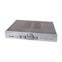
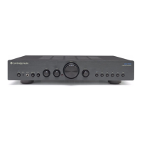
Front Panel Assembl
AP14159/1 Sub Panel 1 Fasten in place between the Ledges of the Front Panel, Align
U
The Power Button Holes
AP12931/1 Li
ut select LEDs
AP12931/1 Li
uide (half of) 0.5 Fasten To Sub
late. Power LED
M3 X 6 Pozi Pan St
late
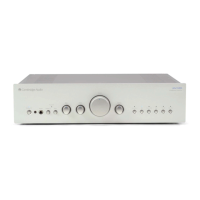
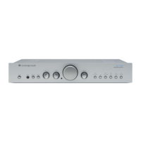
PY638 AP14157/1 Front Panel (Punched And Printed) Silver 1 Extrusion Details AP12738* & Screened With Artwork
AP14826/1 & AP14828/2
AP12935/1 IR Lens 1 Glued In Place On The Front Panel
M3 X 6 C/S Pozi Machine Screw 7 Fasten The Sub Plate to the Front Panel. Only 7 screws are
fitted out of a
IR PCB Assembly (part of F/P PCB assembly) 1 Fitted onto the Front Panel, bom is AP15185/2
lon M3, 1mm Thk 1 Fitted between Front Panel and IR PCB
M2.6 x 4mm Pan hd Poz Ta
tite 1 Use to fix IR PCB onto SubPanel
AP12934/1 7mm TAC Switch Cushion 6 Position on the 7mm tact switch Buttons, down the main
shaft affix usin
rovided on the cushion.
AP12925/1 7mm TAC Switch Button 6 Position In Place On The Front Panel
AP12926/2 7mm Push Switch Button 2 Fitted to SW1 & 2 on main PCB
PCB Gerber AP1
Front Panel & MicroController PCB Assembly
BOM
1 Fixes onto the Sub Panel With M3 M/C Screws. Built to BOM
AP 15185/2
M3 X 6 Pozi Pan Machine Screw 7 Used For Fixing The Front Panel Pcb's To The Subplate
Standoff's
Side Panel Assembl
AP12725/2 Pressed Side Panel (2 Rid
e) 2
AP12727/1 Front Plastic Support (2 Ridge With Captive
M2.6 Nuts
2 Position at Front within Side Panels
AP12728/1 Rear Plastic Support (2 Ridge With Captive M2.6
Nuts
2 Position at Rear within Side Panels
M2.6 X 8 C/S Pozi Plastite 8 To Affix Side Panels To Plastic Inserts
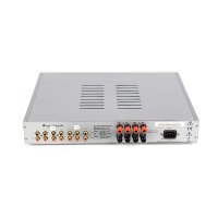
Rear Panel Assembl
AP14162/2 Rear Panel Printed 1 Screened With Artwork AP14830/3
M3 X 10 Pozi Pan Plastite 8 To fix speaker terminal and Phono sockets connectors to
Rear Panel
M4 X 8 Pozi Pan Plastite 2 To fix IEC Power connector to Rear Panel
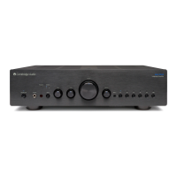
Cambridge Azur 340A Main Assembly BOM