The relays on the other PCBs are controlled by a set of shift registers that convert serial data from the
PIC into 32 latched outputs. Four shift registers (U3,U4,U5,U6) are connected so that the serial input
enters the rst register and is clocked through and out of its serial output into the serial input of the
second register. Changing any output requires 32 bits to be clocked through the registers by the SERIAL
CLOCK signal. When SERIAL STROBE goes high the data is latched in each register to give a static
output. Data appears at the outputs only when the SHIFT REG ENABLE line is high. This line is kept
low at start-up to prevent random data at the outputs, and only goes high when the PIC has initialised
the shift registers.
The RS232 interface is used to control the amplier and can also be used to reprogram the main PIC.
The interface consists of Q3 and Q4. Q3 handles incoming RS232 data, providing a level-shift from
RS232 levels (nominally +/-9V) to PIC levels (+5V/0V). Q4 handles outgoing RS232 data, level shifting it
to give a +15V/0V output.
The main PIC is reprogrammed by holding the standby/ON button in when the mains power is turned
on. The word DOWNLOAD appears on the LCD. A PC running a Windows program is used to
download the program.
The Hub PIC can in turn be reprogrammed by the main PIC. This is done by the PGM, MCLR HUB,
PROGRAM_DATA, and PROGRAM_CLOCK lines that go to the Hub PCB via CN3.
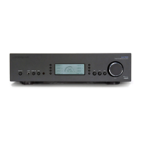
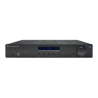
The Input PCB
The input PCB carries:
Input buers
Input select relays
Tape out buer
Input amplier +6 dB
Hub input switcher
Relay drivers
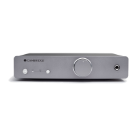
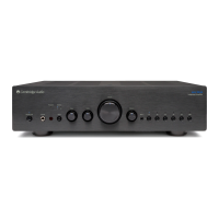
The input PCB has one stereo input (Input 1) that accepts both balanced and unbalanced signals, and six
more unbalanced stereo inputs. There is a further input for tape monitor use. There is a tape output,
taken from before the tone and volume controls, and a preamp output taken from after the tone and
volume controls.
All component numbers here refer to the Left channel.
The A-BUS hub also uses the amplier inputs. The required input is selected separately from the main
amplier input by the CMOS switching IC U1. This is controlled by serial data from the microcontroller
on the hub PCB, in response to switch presses or IR commands.
The relays are driven from an 8-bit serial-in parallel-out (SIPO) shift register on the front panel PCB.
The eight logic signals come in on CN8 and control the 7-way open-collector relay driver U16. The
eighth relay is controlled by Q1.
53