Do you have a question about the CAME 803XC-0010 and is the answer not in the manual?
This document describes the 803XC-0010 device, a control unit designed for various applications, likely related to industrial or commercial settings given its power specifications and control features. The manual provides general precautions, technical specifications, and detailed instructions for its use and maintenance.
This product is intended for specifically indicated use. Any other use is hazardous. Operations indicated in this manual must be carried out exclusively by skilled and qualified personnel and in full compliance with current regulations. Ensure the main power supply is disconnected during all installation procedures.
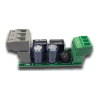
The device is an Interfaccia STRIP LED R/G (STRIP LED R/G Interface). This suggests it is used to control or interface with Red/Green LED strips, likely for signaling or illumination purposes.
| Model | 803XC-0010 |
|---|---|
| Board power supply (V) | 24 AC/DC |
| Maximum output current (A) | 0.5 |
| Working temperature (°C) | -20 ÷ +55 |
The device features several electrical connections, indicated by different colors:
The device supports various configurations, primarily through its ZL37 / ZL38 control boards.
Use DIP 3 to select the barrier status indication mode. This implies that the device can be configured to display the status of a barrier (e.g., open/closed) using the connected LED strips.
Set the F15 function to select the barrier status indication mode. This suggests an alternative or additional method for configuring the barrier status indication, possibly offering more granular control or different display options.
The device utilizes LED signaling for various operational statuses, which can be configured via the ZL37, ZL38, and ZL39 control boards.
This indicates that the ZL37 board controls the Red and Green LEDs to signal the state of an automation system. Red LEDs signify that the automation is closed and possibly in motion, while Green LEDs indicate that the automation is open.
For the ZL38 and ZL39 boards, the signaling differs slightly. Red LEDs flashing indicate that the automation is closed and in movement, while Green LEDs on still signify that the automation is open. The flashing red LEDs could provide a more dynamic or urgent indication compared to a solid red light.
It is important to dispose of the packaging and the device at the end of its life cycle responsibly, in compliance with the laws in force in the country where the product is used. Recyclable components are marked with a symbol and the material's ID marker.
THE DATA AND INFORMATION IN THIS MANUAL MAY BE CHANGED AT ANY TIME AND WITHOUT NOTICE.
THE MEASUREMENTS, UNLESS OTHERWISE STATED, ARE IN MILLIMETERS.
This device is designed to be user-friendly in terms of configuration and status indication, making it suitable for applications requiring clear visual feedback on automation states. The use of DIP switches and specific functions (F15) on different control boards allows for flexible customization to meet various operational requirements. The robust working temperature range (-20 to +55 °C) suggests its suitability for a wide array of environments, including those with moderate temperature fluctuations. The low maximum output current (0.5 A) indicates that it is likely intended for controlling low-power LED strips, consistent with signaling applications rather than high-intensity illumination.
| Brand | CAME |
|---|---|
| Model | 803XC-0010 |
| Category | Gate Opener |
| Language | English |