The provided document is an installation manual for the CAME BK and BKE series of automation systems for sliding gates.
Function Description
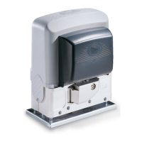
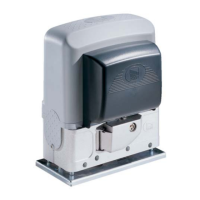
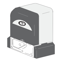
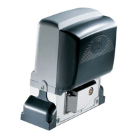
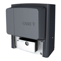
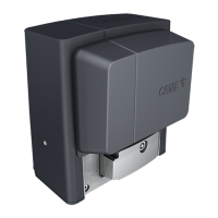
The CAME BK-BKE gearmotor is designed to automate sliding gates for residential and condominium complexes. It is a non-reversible electromechanical gearmotor, housed in a case made partly of cast aluminum and partly of ABS plastic, which also contains the electronic control card and transformer. The system is designed to comply with safety standards and includes various features for gate operation and safety.
The control board, ZBK-ZBKE, manages the gate's movement, safety devices, and various programmable functions. It is powered by 120V a.c. or 230V a.c. and includes a 1A fuse for 24V accessories. The board autonomously controls a safety function that senses obstacles, stopping the gate when opening and triggering automatic closing, or inverting the direction of movement until fully open when closing. After three consecutive inversions during closing, the gate remains open, requiring manual or remote closure.
The system supports various command inputs, including stop buttons, key selectors, and remote controls, allowing for full or partial gate opening and closing. It also incorporates pre-flashing during opening/closing, a courtesy lamp, and a phase lamp.
Important Technical Specifications
The BK-BKE series offers several versions, differing in capacity and module type:
- BK 800: M4 pinion module, max capacity 800 kg.
- BK-BKE 1200/1210: M4 pinion module, max capacity 1200 kg.
- BK-BKE 1800/1810: M4 pinion module, max capacity 1800 kg.
- BK-BKE 2200/2210: M6 pinion module, max capacity 2200 kg.
General Specifications:
- Maximum Gate Weight: 2200 kg.
- Maximum Gate Length: 13 meters.
- Operating Time (Interval): Fixed at 150 seconds.
- 24V Accessories Power Consumption: Max 20W.
- Operating Temperature: -20°C to +55°C.
- Protection Level: IP54.
Model-Specific Electrical and Performance Data:
- BK-800: 21 Kg, 230 V a.c., 4.5 A, 520 W, intensive service, 28 Nm max torque, 800 N push, 22 µF condenser.
- BK-BKE 1200: 18 Kg, 230 V a.c., 3.3 A, 380 W, 31 Nm max torque, 850 N push, 25 µF condenser.
- BK-BKE 1210: 18 Kg, 120 V a.c., 5.6 A, 310 W, 31 Nm max torque, 850 N push, 100 µF condenser.
- BK-BKE 1800: 19.5 Kg, 230 V a.c., 4.2 A, 480 W, 50% duty cycle, 42 Nm max torque, 1/31 reduction ratio, 1150 N push, 10.5 m/min max speed, 31.5 µF condenser.
- BK-BKE 1810: 19.5 Kg, 120 V a.c., 8 A, 440 W, 50% duty cycle, 40 Nm max torque, 1/31 reduction ratio, 1100 N push, 10.5 m/min max speed, 140 µF condenser.
- BK-BKE 2200: 21 Kg, 230 V a.c., 5.1 A, 580 W, 54 Nm max torque, 1500 N push, 35 µF condenser.
- BK-BKE 2210: 21 Kg, 120 V a.c., 9.1 A, 500 W, 51 Nm max torque, 1400 N push, 160 µF condenser.
Cable Specifications (Minimum Thickness):
- 120V-230V 2F power supply: 3G x 1.5 mm² (up to 10m), 3G x 2.5 mm² (10-20m), 3G x 4 mm² (20-30m).
- 230V flashing lamp: 2 x 0.5 mm² (up to 10m), 2 x 1 mm² (10-20m), 2 x 1.5 mm² (20-30m).
- Photoelectric cells TX/RX: 2 x 0.5 mm² / 4 x 0.5 mm² (all lengths).
- 24V power supply accessory: 2 x 0.5 mm² (up to 20m), 2 x 1 mm² (20-30m).
- Control button: 2 x 0.5 mm² (all lengths).
- Antenna connection: RG58 (max 50m).
Usage Features
The system offers extensive customization through DIP switches on the control board:
- Automatic Closing: Activates a timer for automatic gate closure after opening.
- Operating Modes: "Open-stop-close-stop" or "Open-close-inversion" with button/remote control.
- "Open Only" Remote Control: Restricts remote control to opening only.
- "Maintained Action" Function: Requires continuous button press for gate operation.
- Pre-flashing: Flashing light for 5 seconds before gate movement.
- Obstacle Sensor: Prevents gate movement if safety devices detect an obstacle when the motor is not running.
- Reopening/Re-closing during movement: Safety devices can trigger inversion of direction during closing (full opening) or opening (full closing).
- Partial Stop: Gate stops completely, triggering automatic closing.
- Total Stop: Stops the gate and excludes automatic closing; requires manual restart.
- Slave Function: Deactivates master control for coupled gate systems.
- Partial Opening Function: Adjusts partial opening time (fixed 8 seconds or adjustable via trimmer).
- Photocells' Safety Test: Enables the control unit to test safety device efficiency.
- Master Function: Activates master control for coupled motors.
- Limit Switch Programming (ZBKE series): Dedicated function for setting gate travel limits.
- Courtesy/Phase Lamp: Activates external lamps for a fixed time or during gate movement.
Adjustments:
- Motor Torque Limiter: Adjustable via a faston connection (4 positions from min to max).
- Automatic Closing Time (A.C.T. Trimmer): Adjustable from 1 to 150 seconds.
- Partial Opening Time (PAR. OP. Trimmer): Adjustable from 1 to 14 seconds.
Manual Release:
In case of power failure or malfunction, the gearmotor can be manually released using a key to disengage the motor, allowing the gate to be moved by hand. Re-locking is done by turning the key back until the pin settles.
Coupled Gear Motors (Single Control):
The system supports two coupled gear motors with a single control. One motor is designated as "master" (controlling both gates) and the other as "slave." The master board handles all control functions and radio-frequency reception, while the slave board's functions are mostly deactivated.
Maintenance Features
Periodic Maintenance:
The unit generally does not require specific maintenance. However, for precautionary measures or intensive use, it is recommended to:
- Periodically (every six months) check the electric cables for good condition.
- Ensure all bolts and nuts are tight.
- Oil the contact areas between fixed and mobile sliding pieces.
All checks should be recorded in a dedicated logbook.
Problem Solving:
The manual provides troubleshooting steps for common issues:
- Gate Does Not Move: Check power supply (120V/230V AC on L-N terminals), fuses, 24V power on 10-11 terminals, stop button connection (DIP 10 ON if not used), safety device connection (DIP 8 ON if not used), and ensure the blocking/release access panel is closed.
- Gate Remains in Open Position: Check if automatic closure is disabled (DIP 1), verify command devices, ensure no obstructions to safety devices, and confirm all N.C. contacts are set to ON if not used.
Demolition and Disposal:
CAME CANCELLI AUTOMATICI S.p.A. adheres to UNI EN ISO 14001 standards for environmental protection.
- Packaging: Components like cardboard and plastic are solid urban waste and can be disposed of easily, with recycling encouraged.
- Product: The product consists of various materials (aluminum, plastics, iron, electrical wires) that can be disposed of in normal garbage collection bins or recycled in authorized centers. Other components (electrical boards, remote control batteries) may contain polluting substances and should be removed and given to qualified service companies for proper disposal.
Specific regulations in force at the installation location should always be checked for proper disposal.