EasyManua.ls Logo

CAME BK-BKE

CAME BK-BKE
24 pages
To Next Page IconTo Next Page
Loading...
Documentazione
Tecnica
S04
rev. 3.2
06/2003
©
CAME
CANCELLI
AUTOMATICI
BK-BKE
CANCELLI AUTOMATICI
ITALIANO/ ENGLISH/ ESPAÑOL
119BS04-1
SERIE BK |
BK SERIES
|
SERIE BK
2 x 1 - TX
2 x 1
2 x 1.5
8
6
5
9
3
1
2
4
9
10
10
11
3 x 1.5 / 230V
3 x 1.5 / 230V
2 x 1 - TX
3 x 1
2 x 1.5
RG58
4
8
7
6
5
9
3
1
2
4
9
10
10
2 x 1 - TX
2 x 1 - TX
4 x 1 - RX
4 x 1 - RX
11
4 x 1 - RX
Automazioni per cancelli scorrevoli
Automation systems for sliding gates
Automatización para puertas correderas
1 - Gruppo BK
2 - Quadro comando incorporato
3 - Ricevitore radio
4 - Alette finecorsa
5 - Cremagliera
6 - Selettore a chiave
7 - Lampeggiatore di movimento
8 - Antenna di ricezione
9 - Fotocellule di sicurezza
10 - Colonnina per fotocellula
11 - Fermo anta
1 - BK unit
2 - Control panel (incorporated)
3 - Radio receiver
4 - Limit switch tabs
5 - Rack
6 - Key-operated selector switch
7 - Flashing light indica-ting door movement
8 - Antenna
9 - Safety photocells
10 - Photocell column
11 - Closure stop
1 - Conjunto BK
2 - Cuadro de mando incorporado
3 - Radiorreceptor
4 - Aletas de tope
5 - Cremallera
6 - Selector mediante llave
7 - Lámpara intermitente de movimiento
8 - Antena receptora
9 - Fotocélulas de seguridad
10 - Columna para fotocélula
11 - Tope puerta
Impianto tipo Instalación tipo
Standard installation
Question and Answer IconNeed help?

Do you have a question about the CAME BK-BKE and is the answer not in the manual?

CAME BK-BKE Specifications

General IconGeneral
ModelBK-BKE
Motor Voltage230 V AC
Operating Temperature-20°C to +55°C
Protection LevelIP54
Protection RatingIP54
Safety FeaturesObstacle detection

Summary

BK-BKE Automation Systems

General Specifications

Model and Version Overview

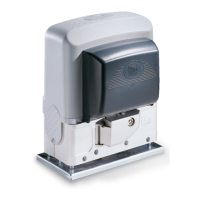
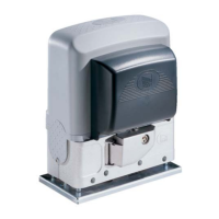
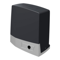
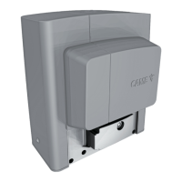
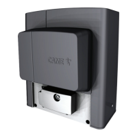
Details on available models, versions, and their specifications.

Technical Characteristics Table

Detailed technical data including power, torque, and speed.

Overall Dimensions Diagram

Diagrams and measurements for physical installation planning.

Pre-Installation Guidelines

Motor Base Anchorage

Instructions for securely fixing the motor unit base to the ground.

Unit Installation Procedures

Vertical and Horizontal Adjustments

Steps for aligning and leveling the unit for proper operation.

Attaching the Rack and Limit Switches

Attaching Limit Switch Tabs

Motor Release and Safety

ZBK-ZBKE Base Board Technical Description

Safety Features and Connections

Details on safety devices, photocell connections, and their functions.

Selectable Functions Overview

Description of various operational functions configurable via dip-switches.

Adjustment Trimmers

Explanation of trimmer functions for parameter adjustment.

ZBK-ZBKE Motherboard Technical Description (English)

Safety Features and Functions

Information on safety system checks and obstacle detection.

Additional Functions Explained

Explanation of automatic closing, partial opening, and other operational modes.

Parameter Adjustment Guide

Details on setting various operational parameters using trimmers.

ZBK-ZBKE Base Board Technical Description (Spanish)

Safety Features and Connections

Information on safety devices, photocell connections, and functions.

Additional Functions Explained

Description of selectable operational functions like automatic closing.

Parameter Adjustment Guide

Explanation of trimmer functions for partial opening and automatic closing.

Main Components Identification

Photocell Function Test Procedure

Electrical Connections Guide

Limit Switch Connections

Motor Torque Limiter Settings

Limit Switch Programming

Function Selection via Dip-Switches

Two Combined Motors: Installation and Connections

Radio Control Installation

Transmitter Encoding and Configuration

Transmitter Code Storage

Manufacturers Declaration and Compliance

Related product manuals