Do you have a question about the CAME BK 1800 and is the answer not in the manual?
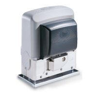
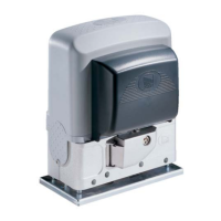
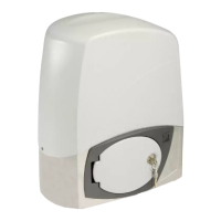
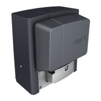
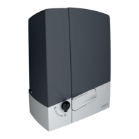
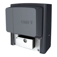
The BK-BKE gearmotor is designed to automate sliding gates for residential and condominium complexes.
Maximum gate weight 2200 kg with maximum length of 13 meters.
The BK-BKE gearmotor is designed and built by CAME CANCELLI AUTOMATICI S.p.A. and meets safety standards.
Provides technical specifications and data for the BK-BKE gearmotors.
Description of the gearmotor unit components and accessories with their references.
Provides measurements of the gearmotor unit in millimeters.
Important checks to perform before installing the gate operator to ensure safety and proper function.
Lists the necessary tools and materials required for safe and correct installation.
Details the types of cables and their minimum thickness for various connections.
Instructions and guidelines for securely anchoring the gear motor unit to the base foundation.
Details on the initial phase of installation, including feet adjustment and alignment.
Procedure for attaching the gate rack to the pinion and adjusting the play between them.
Instructions for positioning the limit-switch tabs on the rack to determine gate travel limits.
Procedure for manually releasing the gearmotor using keys A and B.
Overview of the control board's power, functions, and safety features, including LED indicators.
Identification and description of the main components and terminal blocks on the control board.
Diagrams and instructions for connecting the gear motor, limit switch, and encoder.
Wiring diagrams for connecting stop buttons, key selectors, and command buttons.
Wiring diagrams for courtesy lamps, phase lamps, indicator lights, and flashing lights.
Wiring diagrams for connecting safety devices like photocells and safety edges.
Diagrams for connecting electric power, fan, and 24V accessories.
Diagrams showing how to check the operating state of photocells and their connections.
Instructions on how to adjust the motor torque limiter using the black wire.
Details on adjusting Automatic Closing Time (A.C.T.) and Partial Opening Time (PAR.OP.).
Guide to selecting various functions using the dip-switches on the control board.
Steps to prepare the AF radio board, including jumper settings and insertion into the motherboard.
Instructions for codifying different types of CAME remote transmitters.
Procedure for assigning codes to TOP Quartz series transmitters like T262M, T264M.
Steps to set codes for T264M and T304M transmitters.
Instructions for setting codes for T2622M and T3022M transmitters.
Procedure for codifying ATOMO series remote transmitters.
Instructions for codifying TOUCH series remote transmitters.
Procedure for memorizing transmitter codes onto the control board for CH1 and CH2.
Guidelines for periodic checks and maintenance of the unit, recommended every six months.
Troubleshooting common issues with the gate, such as not moving or remaining open.
Recommendations for the proper disposal of packaging materials.
Guidelines for the safe and responsible disposal of the product and its components.
Declaration of conformity with relevant directives and harmonized standards.
| Brand | CAME |
|---|---|
| Model | BK 1800 |
| Category | Gate Opener |
| Language | English |