Do you have a question about the CAME BK 1200 and is the answer not in the manual?
Identifies the CAME BK series automation for sliding gates and its CE marking.
Explains symbols indicating important, safety, and general information.
Defines intended use for residential/condominium sliding gates and operational limits like weight and length.
Lists standards and directives the product adheres to for safety and quality assurance.
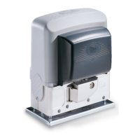
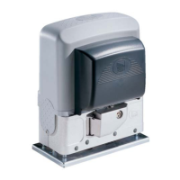
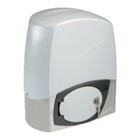
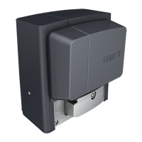
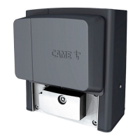
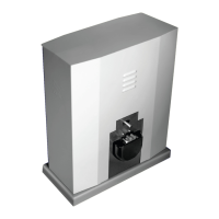
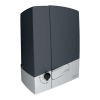
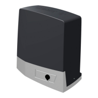
Describes the gearmotor construction, versions, and available accessories.
Presents key technical data including weight, power, torque, speed, and temperature ratings.
Lists and illustrates the individual parts of the gearmotor assembly.
Lists optional accessories that can be used with the gearmotor unit.
Provides the physical measurements of the gearmotor unit in millimeters.
Essential checks for gate, track, and mounting location prior to installation.
Lists the necessary tools and materials for a safe installation.
Details minimum cable thicknesses for electrical connections based on length.
Instructions for creating a foundation and securing the gearmotor to the base.
Steps for positioning and aligning the unit, including feet adjustment and guide rail connection.
Guide on attaching the rack to the gate, adjusting the pinion-rack interface, and setting limit switch tabs.
Explains how to manually disengage the gearmotor for gate movement or maintenance.
Details the control board's power, fuses, operating time, and safety functions.
Identifies key components and terminals on the ZBK/ZBKE control board with a diagram.
Illustrates electrical connections for the gear motor, limit switches, and encoder for both BK and BKE series.
Provides specific wiring adjustments for installing the gear motor on the right side of the gate.
Shows how to connect various control devices like stop buttons and key selectors to the board.
Details connections for courtesy lamps and phase lamps to indicate gate status.
Explains how to connect safety devices like photocells and safety edges to the control board.
Covers main power input, ground connection, fan output, and 24V accessory power output.
Details the electrical connection for checking photocell operating status and related dip switch settings.
Explains setting the motor torque limiter and adjusting automatic closing/partial opening times.
Details the function of each dip-switch for configuring automatic closing, safety features, and operation modes.
Step-by-step guide for programming limit switches on the ZBKE control board.
How to connect and configure two gear motors to operate together using a single control board.
Details the preparation and insertion of the AF radio frequency board for remote control functionality.
Explains how to set up various transmitter models (TOP, ATOMO, TOUCH) to match the control board.
Describes the procedure to store transmitter codes on the control board using CH1 and CH2.
Recommends routine checks every six months for optimal unit performance.
Provides solutions for common issues like the gate not moving or remaining open.
Guidance on proper disposal of packaging and product components according to environmental standards.
Includes the manufacturer's declaration of conformity and warranty information.
| Brand | CAME |
|---|---|
| Model | BK 1200 |
| Category | Gate Opener |
| Language | English |