
C
carraaronAug 1, 2025
What to do if CAME BY-3500T opens but does not close?
- SscarrAug 2, 2025
If your CAME Gate Opener opens but doesn't close, the photocells might be engaged. Check that the photocells are clean and working correctly.
What to do if CAME BY-3500T opens but does not close?
If your CAME Gate Opener opens but doesn't close, the photocells might be engaged. Check that the photocells are clean and working correctly.
Why my CAME Gate Opener does not open or close?
If your CAME Gate Opener isn't opening or closing, the possible reasons include: * **No Power:** Ensure the unit is receiving mains power. * **Gearmotor Unlocked:** Make sure the gearmotor is locked. * **Transmitter Battery:** Replace the batteries in the transmitter.
What to do if my CAME BY-3500T Gate Opener opens but does not close?
If your CAME Gate Opener opens but doesn't close, it might be due to the photocells being engaged. Check that the photocells are clean and working correctly.
Why CAME BY-3500T does not open or close?
If your CAME Gate Opener isn't opening or closing, here are some potential causes: * **No power:** Ensure the gate opener is receiving mains power; check the power supply. * **Gearmotor unlocked:** The gearmotor may be unlocked; make sure to lock it. * **Transmitter battery flat:** If the transmitter battery is flat, replace it with a new one.
Steps to prepare the installation site, including digging and conduit setup.
Instructions for positioning and securing the anchoring plate for the operator.
Steps for placing and adjusting the operator unit onto the anchoring plate.
Procedure for attaching the gate rack to the gate leaf, engaging with the pinion.
Details on adjusting the distance and alignment between the pinion and the rack.
Final steps to secure the operator unit to the anchoring plate after alignment.
Instructions for positioning and securing limit switch tabs for gate travel endpoints.
Guidelines for routing and connecting electrical cables to the operator.
Details on connecting the operator to a 400V AC three-phase power source.
Standard and safety test connection diagrams for DELTA photocells.
Connection diagrams for DIR and DELTA-S photocells, including safety test configuration.
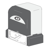
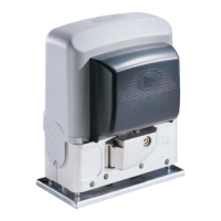
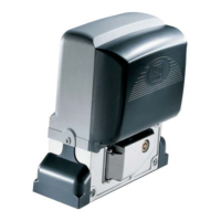
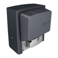
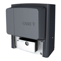
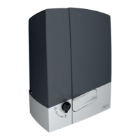
The CAME BY-3500T is a robust sliding-gate operator designed for industrial applications. This device is a partly completed machine, meaning it is intended to be incorporated into or assembled with other machinery or equipment to form a complete system that complies with the Machinery Directive (2006/42/EC) and European reference standards. Its primary function is to automate the opening and closing of sliding gates, providing a reliable and efficient solution for managing access in industrial environments.
The BY-3500T operator features a 400 V AC three-phase motor, which provides substantial power for handling heavy sliding gates. It is equipped with a control board that manages all operational aspects, including motor control, safety device integration, and command processing. Mechanical limit switches are integrated to accurately define the gate's travel end points, ensuring precise stopping at both open and closed positions. The system supports various command and control devices, such as STOP buttons, open commands, partial opening commands, close commands, and step-by-step commands, allowing for flexible operation tailored to specific site requirements.
Safety is a paramount aspect of the BY-3500T's design. The control board allows for the integration of multiple safety devices, including photocells (like DELTA, DIR/DELTA-S, DXR/DLX models) and sensitive edges (DFWN). These devices are crucial for detecting obstacles in the gate's path, preventing collisions, and ensuring the safety of personnel and property. The system can be configured to perform safety device tests, verifying their correct operation after each opening and closing command.
The operator also includes signalling devices to enhance visibility and awareness during gate movements. These can include additional lights to illuminate the manoeuvring area, flashing beacons that activate during opening and closing, and operator status warning lights to indicate whether the gate is open or closed.
For installations requiring control over two gates, the BY-3500T supports a paired operation mode. In this configuration, two operators can be controlled by a single command, with one designated as the MASTER and the other as the SLAVE. This allows for synchronized movement of two gates, which is particularly useful for wide entrances or specific access control scenarios. The MASTER unit manages all commands and safety devices, while the SLAVE unit follows its instructions.
The control board features DIP switches for programming various functions, such as automatic closure, sequential and step-by-step commands, hold-to-run operation, pre-flashing, and obstacle detection with the motor stopped. Trimmers are provided for fine-tuning parameters like automatic closing time and partial opening duration, offering customization to suit different operational needs.
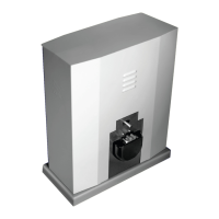
The BY-3500T is designed for ease of installation and configuration, though it requires skilled and qualified personnel to ensure compliance with safety regulations and professional practices. The installation process involves preparing a foundation frame, laying an anchoring plate, and securely mounting the operator. Careful attention is paid to the pinion-rack coupling, which can be adjusted vertically and horizontally to ensure smooth and efficient gate movement.
The system's electrical connections are clearly defined, with provisions for mains power supply, motor power supply, and various accessories. All connections are protected by quick fuses, and the manual emphasizes the importance of disconnecting the main power supply before any work on the control panel. Cable cross-sections are specified based on cable length and power draw, ensuring safe and reliable electrical performance.
The BY-3500T can be installed on either the left or right side of the gate. If installed on the right, the motor and limit switch phases can be reversed through a simple configuration, demonstrating its adaptability to different site layouts.
The radio control feature allows for convenient remote operation. An AF card can be fitted to the control board, enabling the storage of up to 25 users. The system supports different operating modes for radio control, including opening only the MASTER gate or opening both MASTER and SLAVE gates simultaneously, depending on the command issued from the transmitter.
While the manual primarily focuses on installation and initial setup, it implicitly highlights several features that contribute to the device's maintainability and longevity. The robust construction and industrial-grade components suggest a design intended for continuous operation in demanding environments. The clear layout of the control board and accessible terminal blocks simplify troubleshooting and component replacement, should it be necessary.
The instruction to keep the manual inside the technical folder along with other device manuals underscores the importance of having readily available information for future maintenance and servicing. The emphasis on checking the mechanical condition of the guided part and ensuring correct opening and closing prior to installation also serves as a preventative measure, reducing the likelihood of premature wear or malfunction.
The product's average life, stated as 150,000 cycles under normal usage and maintenance conditions, indicates its durability. The requirement for periodic checks of safety and protection devices, as well as the manual release mechanism, ensures that critical safety functions remain operational throughout the device's lifespan. In case of malfunction, users are directed to contact customer services, indicating a support structure for maintenance and repair. The provision of a production batch on the product label facilitates tracking and support.
| Power Supply | 230 V AC |
|---|---|
| Operating Temperature | -20°C to +55°C |
| Protection Class | IP54 |
| Motor Voltage | 230 V AC |
| Protection Level | IP54 |
| Safety Features | Obstacle detection |
| Control Options | Remote control |