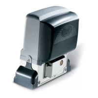
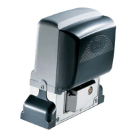
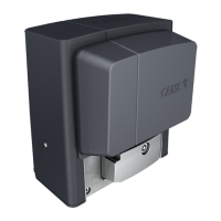
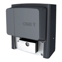
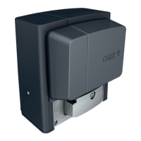
The provided manual describes the CAME BX-246 automation system for sliding gates. This device is designed for residential and condominium use, capable of handling gates up to 600kg in weight and 18m in length.
Function Description
The BX-246 operator is an electromechanical gearmotor that automates the opening and closing of sliding gates. It incorporates an amperometric device for constant monitoring of the motor's drive. In case of an obstacle, the system detects the overload and inverts the gate's movement (opens if closing, closes if opening). After three consecutive obstacle detections, the gate stops in opening mode and disables automatic closing. To resume operation, a command button or remote control must be used.
The control board, ZD2, manages various functions:
- Automatic Closing: Activates after the gate completes an opening cycle. The waiting time is adjustable from 1 to 150 seconds and is conditioned by safety device activation. It does not activate after a total safety "stop" or during a blackout.
- Operating Modes:
- "Open-stop-close-stop" function (DIP switch 2 ON): Allows sequential commands (open, stop, close, stop) via a button or radio transmitter.
- "Open-close" function (DIP switch 2 OFF): Allows sequential commands (open, close) via a button or radio transmitter.
- "Open only" function (DIP switch 3 ON): The gate only opens via a button or radio transmitter.
- Pre-Opening and Closing Flasher (DIP switch 4 ON): The flashing light connected to terminals [10-E1] flashes for 5 seconds before the gate begins to move.
- Obstacle Detection (DIP switch 5 ON): Prevents any gate movement if safety devices (e.g., photocells) detect obstacles while the motor is stopped (gate closed or after a total stop command).
- Maintained Action (DIP switch 6 ON): The gate operates only while a command button (2-3P opening or closing) is continuously pressed.
- Photocells' Safety Test (DIP switch 7 ON): Allows the control board to check the efficiency of safety devices (photocells) after every opening or closing command. If problems are detected, the PROG LED flashes, and radio transmitter commands are canceled.
- Total Stop (DIP switch 8 OFF): Stops the gate and excludes automatic closing. To restart, use the keypad or transmitter.
- Opening During Closing (DIP switch 9 OFF): If photocells detect an obstacle during closing, the gate's motion is inverted until fully opened.
- Partial Stop (DIP switch 10 OFF): Stops the gate when an obstacle is detected by a safety device. Once the obstacle is removed, the gate remains still or closes if automatic closing is activated.
The system also supports partial opening for pedestrian access via a key selector or button connected to 2-3P.
Important Technical Specifications
BX246 OPERATOR:
- Control panel power supply: 230V AC 50/60Hz
- Operator power supply: 24V DC
- Draw: 10 A
- Power: 400 W
- Reduction ratio: 1/33
- Thrust: 700 N
- Max speed: 6÷12 m/min
- Duty cycle: Intensive use
- Protection rating: IP54
- Insulation class: I
- Weight: 15 kg
- Operating temperature: -20°C to +55°C
ZD2 CONTROL BOARD:
- Power supply: 230V - 50/60 Hz
- Maximum power allowed: 400 W
- Absorption at rest: 100 mA
- Maximum power for 24V accessories: 35 W
- Insulation rating: II
FUSE TABLE (ZD2):
- Motor: 10 A-F
- Control board (line): 1.6 A-F
- Accessories: 1.6 A-F
- Command devices: 3.15 mA-F
Cable List and Minimum Thickness:
The manual provides a detailed table for minimum cable thicknesses based on length for various connections, including control panel power, flashing light, photocells, accessories power supply, safety and control devices, and antenna connection. For example, a 230V control panel power supply requires 3G x 1.5 mm² for <10m, 3G x 2.5 mm² for 10-20m, and 3G x 4 mm² for 20-30m.
Usage Features
The BX-246 is designed for ease of use and safety.
- Adjustable Settings: Trimmers on the control board allow adjustment of:
- Automatic closing running time (ACT).
- Partial opening length (PAR.OP.).
- Amperometric sensitivity for slowdown (SLOW S.) and movement (RUN S.) to control motor force and react to obstacles.
- Final opening/closing phase slowdown speeds (SLOW V.).
- Opening/closing motion speed (RUN V.).
- Radio Control: The system supports radio control activation by connecting an AF board and programming transmitters. It also offers a second channel output for accessory devices.
- Manual Release: In case of power failure or malfunction, the gearmotor can be manually released using a trilobed key and turning a handle, allowing the gate to be moved by hand.
- Safety Devices: The system integrates with various safety devices such as photocells and sensitive edges, offering different response behaviors (partial stop, re-open during closing, open while closing) depending on the wiring and DIP switch settings.
Maintenance Features
The manual outlines both periodic and extra-ordinary maintenance procedures.
Periodic Maintenance (every 6 months, by end-user):
- Cleaning: Wipe clean the glass surface of photocells.
- Functionality Check: Check that safety devices work properly. To test photocells, pass an object in front of them during closing; the gate should invert motion or stop. This is the only maintenance procedure to be carried out with power connected.
- Obstruction Removal: Remove any obstructions from the gate's area of operation and photocell beams.
- Lubrication: Lubricate joints with grease if strange vibrations or squeaking occur.
- Anchoring Screws: Check the state of lubrication and tightness of the anchoring screws on the operator.
Extra-ordinary Maintenance (by specialized technicians):
- Any repairs, improvements, or complex maintenance beyond the end-user's scope must be performed by specialized firms. The manual includes a log for recording such interventions.
General Maintenance Guidelines:
- Always cut off the main power supply and disconnect emergency batteries before performing any maintenance, adjustments, or repairs.
- Use a water-dampened cloth for cleaning photocells; avoid solvents or chemicals that could damage the devices.
- If the system exhibits anomalous behavior, stop using it immediately and restore safety conditions before resuming operation.
The manual also provides a troubleshooting guide for common malfunctions, such as the gate not opening/closing, opening but not closing, closing but not opening, or the flasher not working, along with possible causes and remedies.