Page 23 - Manual FA01731-EN - 01/2023 - © CAME S.p.A. - The contents of this manual may be changed at any time and without notice. - Translation of the original instructions
ENABLING THE RADIO CONTROL
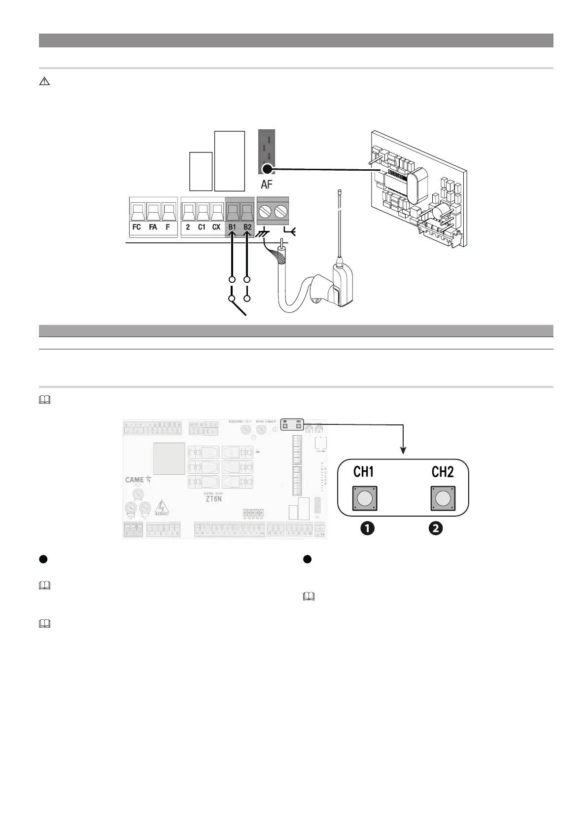
Electrical connections
Before working on the control panel, disconnect the mains power supply and remove the batteries, if any.
Fit an AF card to the control board using the AF connector.
Connect the RG58 cable to the terminals.
Connect up the electrics for the devices and accessories.
AF
Device Output Power supply (V) Maximum current draw (A)*
Auxiliary contact B1 - B2 - 5 (24 V AC/DC)
* resistive loads
Saving users
You can store up to 25 users.
1
Channel CH1
Channel CH1 is used for gate opening and closing commands.
The command depends on the selections made on DIP switches 2-3. See
sequential, step-by-step and open command.
Press and hold the CH1 button.
The LED flashes.
Press a button on the transmitter.
2
Channel CH2
Channel CH2 is used for controlling the accessory device connected to B1-B2.
Press and hold the CH2 button.
The LED flashes.
Press a second button on the transmitter.
 Loading...