Do you have a question about the CAME BK 2200 and is the answer not in the manual?
Defines the intended use of the BK-BKE gearmotor for automating sliding gates.
Specifies the maximum gate weight and length supported by the gearmotor.
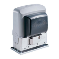
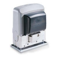
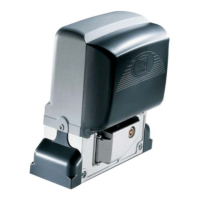
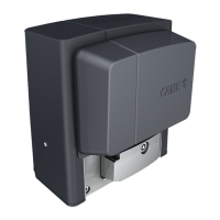
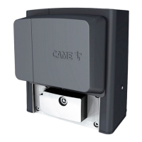
Details the design, construction, and versions of the BK-BKE electromechanical gearmotor.
Provides a table with technical specifications for different BK-BKE gearmotor models.
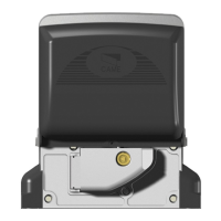
Identifies and illustrates the components of the gearmotor unit and available accessories.
Presents diagrams with measurements of the gearmotor unit in millimeters.
Lists essential checks and safety precautions before proceeding with gate operator installation.
Outlines the necessary tools and materials required for a safe and compliant installation.
Details the minimum cable types and thicknesses required for various connections.
Explains the procedure for securely anchoring the gearmotor to its base foundation.
Guides on positioning and aligning the gearmotor unit for optimal installation.
Describes how to attach the rack to the gate and adjust the pinion for correct operation.
Details the positioning of limit-switch tabs on the rack to define gate travel limits.
Explains the procedure for manually releasing and locking the gearmotor.
Describes the control board's power, protection, and safety functions for automated gates.
Identifies and labels the key components and connectors on the control board.
Provides diagrams and instructions for wiring the gear motor, limit switches, and encoders.
Details wiring for checking photocell operating status, including diagrams for DOC and DIR types.
Explains how to adjust the motor torque limiter to set operational force.
Describes how to adjust automatic closing and partial opening times using trimmers.
Details the functions selectable via dip-switches on the control board for gate operation.
Guides on preparing and installing the AF radio board onto the motherboard.
Explains how to set codes for various CAME transmitter models using dip-switches.
Details the process for memorizing transmitter codes onto the control board's CH1 and CH2 channels.
Recommends periodic checks for electric cables, bolts, and oiling of sliding pieces.
Provides troubleshooting steps for common issues like the gate not moving or remaining open.
| Power Supply | 230 V AC |
|---|---|
| Max Gate Weight | 2200 kg |
| Protection Rating | IP54 |
| Power | 750 W |
| Operating Temperature | -20°C to +55°C |
| Voltage | 230 V AC |
| Maximum Gate Weight | 2200 kg |
| Limit Switch Type | Mechanical |