Do you have a question about the CAME BK Series and is the answer not in the manual?
Highlights critical dangers like high voltage, crushing, and entrapment for safe operation.
Procedure to manually release the gearmotor for gate operation.
Procedure to lock the gearmotor back into place after manual release.
Guidelines for routine cleaning, checks, and maintenance of the operator.
Identifies common problems and their potential causes and fixes.
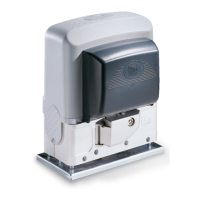
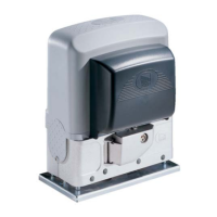
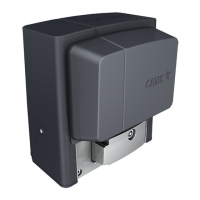
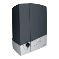
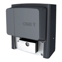
Defines the specific purpose and application of the operator.
Provides detailed technical specifications and performance data.
Illustrates the physical dimensions and measurements of the operator.
Details duty cycle calculations per hour and consecutive cycles.
Presents a graphical representation of cycles per hour based on gate length.
Presents a graphical representation of consecutive cycles based on gate length.
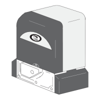
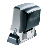
Lists and identifies all components of the operator unit.
Illustrates the general setup and components for standard installation.
Provides essential advice and warnings for qualified installers.
Lists crucial checks to perform before starting the installation process.
Specifies the necessary tools and materials for safe and compliant installation.
Details cable types, minimum sections, and connection requirements.
Instructions for installing protective tubes for electrical wiring.
Instructions for preparing and sinking the foundation frame.
Steps for fitting and fixing the anchoring plate to the foundation.
Steps for preparing the gearmotor before placing it on the plate.
Procedure for placing and adjusting the gearmotor on the anchoring plate.
Instructions for attaching and securing the rack to the gate.
Steps for properly aligning the pinion and rack for smooth operation.
Final steps to secure the gearmotor after adjustments.
Procedure to set the limit switch for the gate's opening position.
Procedure to set the limit switch for the gate's closing position.
Identifies all parts and connectors on the control board.
Details electrical connections, wiring diagrams, and fuse protection.
Illustrates internal factory wiring for gearmotor and limit switches.
Details how to connect the power supply to the control board.
Instructions for connecting signaling devices like flashing lights.
Wiring instructions for various control devices like stop buttons and keypads.
Details on setting up radio control, transponders, and card readers.
Configuring photocell inputs for safety functions like reopening and obstruction detection.
How the control board tests photocell functionality.
Setting up sensitive safety edges for reopening or reclosing functions.
Instructions for fitting the RIO-CONN card for wireless devices.
Instructions for serial RS485 connection via CRP for paired operation.
Explanation of buttons (ESC, <, >, ENTER) used in the programming menu.
Guide to accessing and using various programmable functions (F1-F5).
Configuring maintained action, closing times, and preflashing.
Selecting sensor types and managing serial connections.
Saving/reading data, passing parameters, and setting opening direction.
Configuring wireless inputs and communication speeds.
Adding, deleting users, and setting up code decoding.
Resetting parameters, counting maneuvers, and checking firmware version.
Final steps for putting the operator into service after installation and programming.
Procedure for adding users with associated commands.
Steps for removing single users from the system.
Procedure to save user and configuration data onto the Memory Roll.
Procedure to load saved data from Memory Roll to another control board.
Lists and explains common error codes displayed by the system.
Concluding steps to refit covers and secure the operator.
Instructions for connecting and operating two operators in a paired system.
Environmental guidelines for product dismantling and disposal.
| Motor Voltage | 230 V AC |
|---|---|
| Operating Temperature | -20°C to +55°C |
| Power Supply | 230V AC |
| Motor Power | 300W |
| Limit Switch Type | Mechanical |
| Safety Features | Obstacle detection |