{
{
{
8 88
10”
1”
8 8 8
p. 19 - Manual FA00442-EN - 12/2017 - © CAME S.p.A. - Translated original instructions
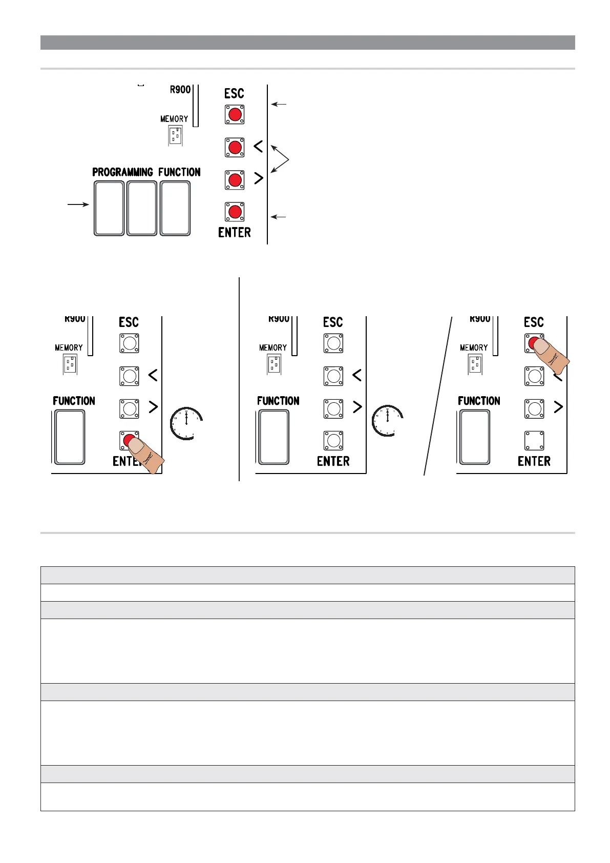
To exit the menu, wait 10 seconds or press ESC.
To enter the menu, keep the ENTER button
pressed for at least one second.
Display
The < > keys are for:
- moving from one item to another;
- increasing or decreasing a value;
- opening and closing the gate (only when testing).
The ESC button is for:
- exiting menus;
- cancelling changes;
- stopping the gate (only when testing).
The ENTER key is for:
- entering menus;
- confirming or memorizing set values.
PROGRAMMING
DESCRIPTION OF THE COMMANDS
F1 Total stop (1-2) OFF (default) / ON
NC input – Gate stop that excludes any automatic closing; to resume movement, use the control device. The safety device is inserted into (1-2).
F2 Input (2-CX) OFF (default) / 1 = C1 / 2 = C2 / 3 = C3 / 4 = C4 / 7 = C7 / 8 = C8 / r7 = r7 / r8 = r8
NC input – Can associate: C1 = reopening during closing by photocells, C2 = reclosing during opening by photocells, C3 = partial stop, C4 =
obstruction wait, C7 = reopening during closing by sensitive safety-edges (with clean contact), C8 = reclosing during opening by sensitive safety-
edges (with clean contact), r7 = reopening during closing for sensitive safety edges (8K2 resistive input), - r8 = reclosing during opening for
sensitive safety edges (8K2 resistive input).
The C3 Partial stop function only appears if the F 19 Automatic closing time function is activated.
F3 Input (2-CY) OFF (default) / 1 = C1 / 2 = C2 / 3 = C3 / 4 = C4 / 7 = C7 / 8 = C8 / r7 = r7 / r8 = r8
NC input – Can associate: C1 = reopening during closing by photocells, C2 = reclosing during opening by photocells, C3 = partial stop, C4 =
obstruction wait, C7 = reopening during closing by sensitive safety-edges (with clean contact), C8 = reclosing during opening by sensitive safety-
edges (with clean contact), r7 = reopening during closing for sensitive safety edges (8K2 resistive input), - r8 = reclosing during opening for
sensitive safety edges (8K2 resistive input).
The C3 Partial stop function only appears if the F 19 Automatic closing time function is activated.
F5 Safety test OFF (default) / 1 = CX / 2 = CY / 4 = CX+CY
After every opening or closing command, the board will check whether the photocells are working properly.
The safety test is always active for wireless devices.
FUNCTIONS MENU
Warning! When programming, the gate must not be operating.

 Loading...