p. 14 - Manual FA00442-EN - 12/2017 - © CAME S.p.A. - Translated original instructions
ELECTRICAL CONNECTIONS
⚠
Warning! Before doing any work on the control board, cut off the mains power supply, and disconnect any batteries.
The functions on the input and output contacts, the time settings and user management, are set and viewed on the graphic display.
All wiring connections are quick-fuse protected.
Fuses ZBKN - ZBKEN
- Line
8 A-F (230 V AC)
15 A-F (120 V AC)
- Card
630 mA-F
- Accessories
1 A-F
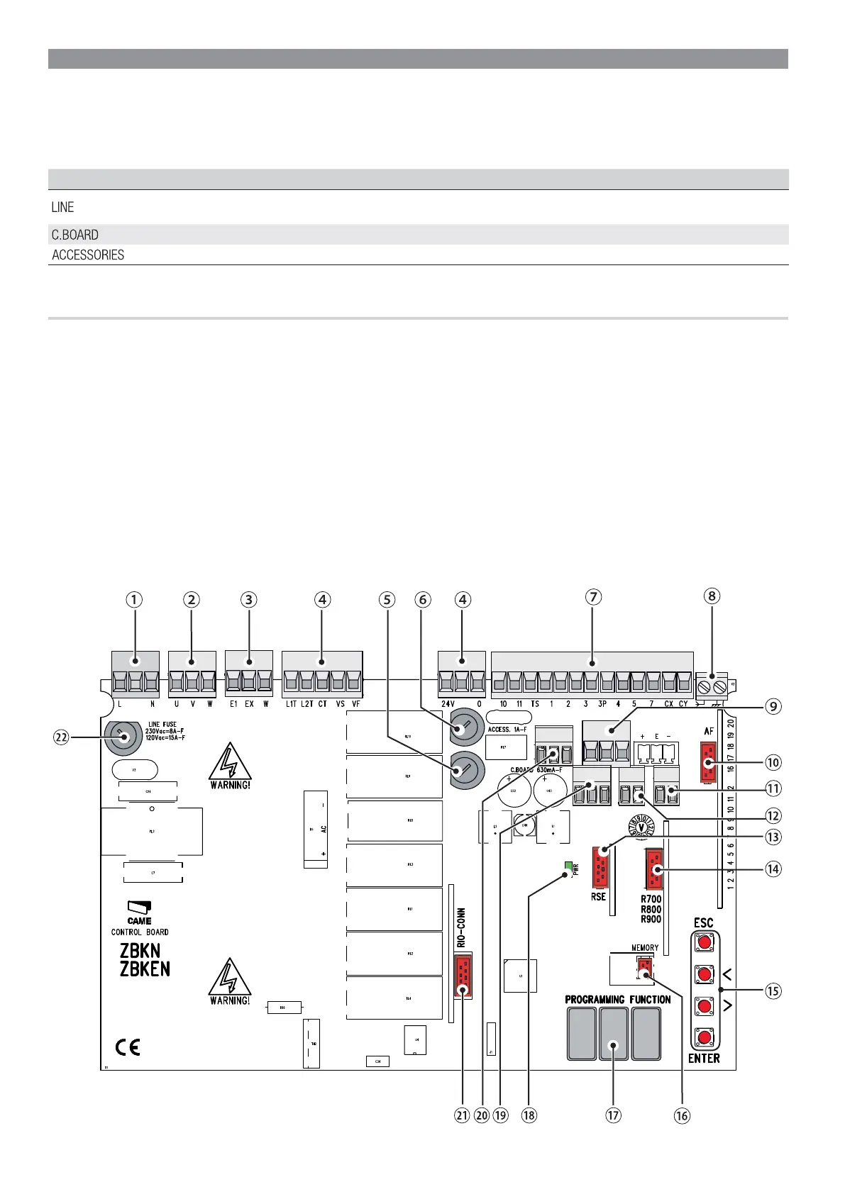
DESCRIPTION OF PARTS
1. Power supply terminals
2. Terminal for gearmotors
3. Terminals for signaling devices
4. Transformer terminals
5. Control-board fuse
6. Accessories fuse
7. Terminals for control and safety devices
8. Antenna terminal
9. Terminals for limit-switch micro-switches
10. AF card connector
11. Terminals for transponder selector
12. Keypad selector terminal
13. RSE board connector
14. Connector for the R700/R800/900 cards
15. Programming buttons
16. Memory roll board connector
17. Display
18. Power supply on warning LED
19. Terminals for paired of CRP connection
20. Terminals for the RGP1 module
21. Connector for the RIO-CONN card
22. Line fuse

 Loading...