MM
MM
MM
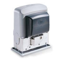
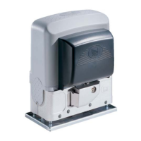
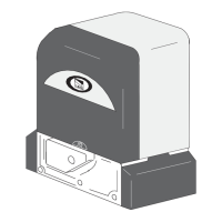
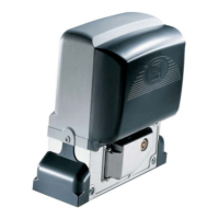
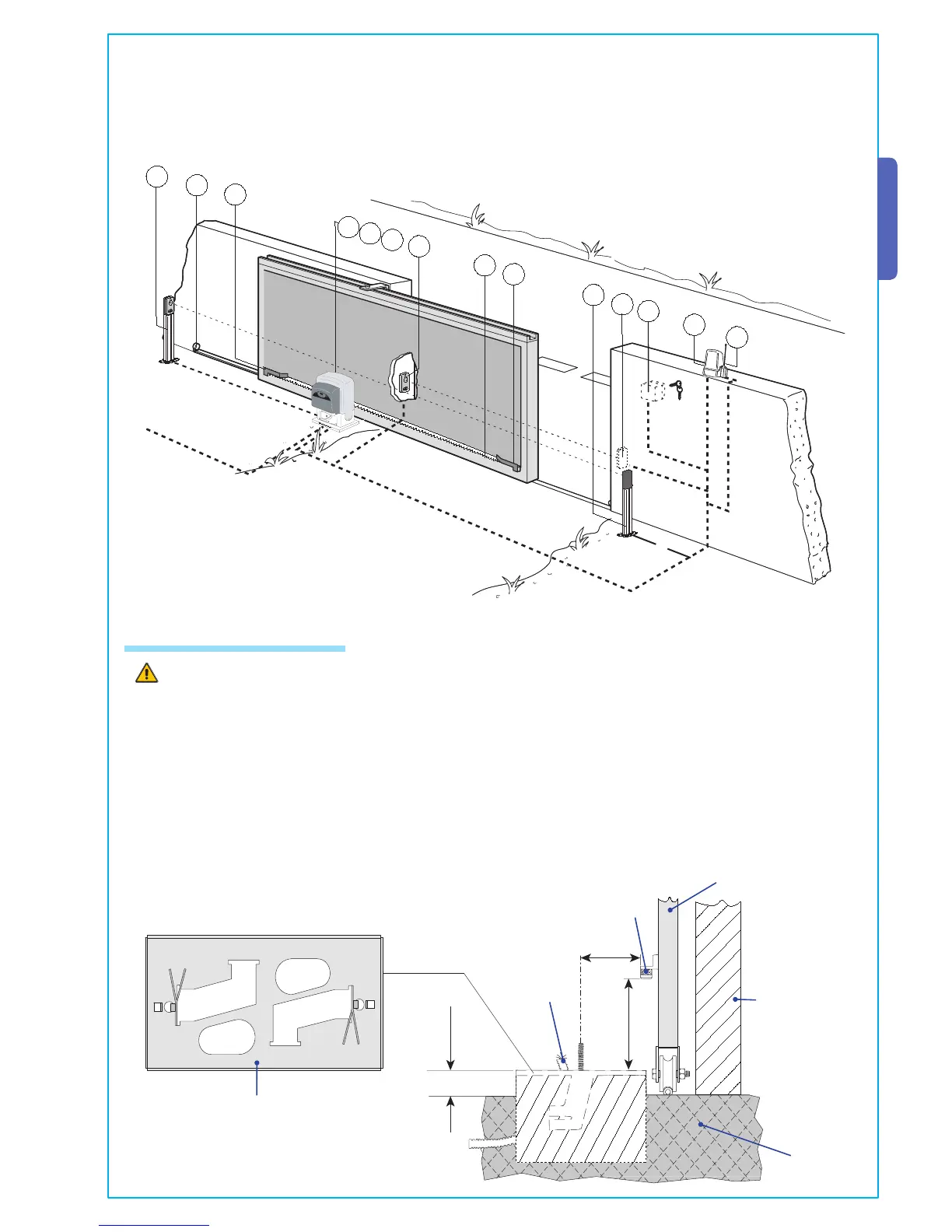
1- BK or BKE unit
2- Control board incorporated
3- Radio receiver
4- Limit-switch tabs (only for the BK unit)
5- Rack
6- Key-operated selector switch
7- Flashing light indicating door movement
8- Antenna
9- Safety photocells
10- Photocell column
11- Closure stop
The following applications are only examples, as the space required for unit installation and the accessories vary de-
pending on dimensions and therefore it is up to the installer to select the best solution.
5.4 Motor to base anchorage
Install the screws in the anchor plate and fasten them with a nut, then bend the preformed clamps downwards.
Construct a cement foundation that is large enough to accomodate the gear motor (it is a good idea to protrude 50 mm. from the
ground). When pouring the foundation, embed the gear motor anchor plate and the relative clamps in the cement.
The anchor bolts should be embedded in the concrete in the positions indicated; the drive unit is then attached to this bots. The
anchor plate must be perfectly level and absolutly clean; the bolts threads must be completly exposed.
N.B.: The fl exible tubes for the electrical wiring must be embedded in the base and protude in the correct position.
Fixing plate / Anchor stays
Cables
Concrete
base
Rack-limit
Gate wing
Wall
5
All the data and information contained herein is considered subject to change at any time and at our discretion
ENGLISH

 Loading...