U2
CARICO
CHIUSO
APERTO
U1
CARICO
APERTO
NC
NA
C
1
2
L
N
M
NC
NA
C
1
2
L
N
NC
NA
C
1
2
U2
CARICO
CHIUSO
APERTO
U1
CARICO
APERTO
NC
NA
C
1
2
L
N
M
NC
NA
C
1
2
L
N
NC
NA
C
1
2
NC
NA
C
1
2
230V~
230V~
NC
NA
C
1
2
L
N
M
NC
NA
C
1
2
L
N
E
F
G
H
I
230V~
230V~
Pag. 6 - Manuale FB00801-IT - ver. 1 - 07/2017 - © CAME S.p.A. - I contenuti del manuale sono da ritenersi suscettibili di modifica in qualsiasi momento senza obbligo di preavviso.
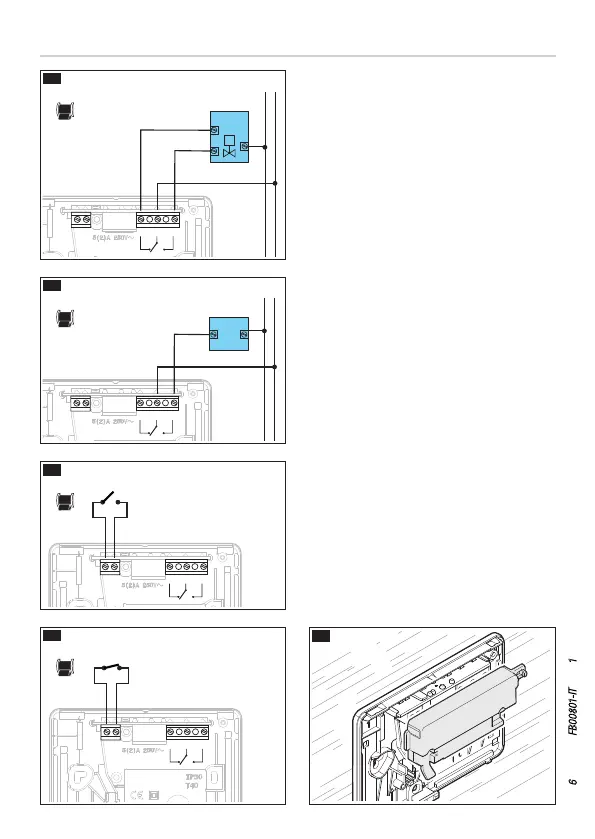
I collegamenti vanno eettuati in funzione
del tipo di apparecchiatura comandata dal
cronotermostato.
LEGENDA
Conduttori di alimentazione da rete.
N = neutro.
L = fase.
Contatti del relé.
C = comune.
NA = contatto normalmente aperto.
NC = contatto normalmente chiuso.
Carichi
U1 = bruciatore, pompa di circolazione,
elettrovalvola, ecc.
U2 = valvola motorizzata.
Ingressi per comando remoto o contatto
magnetico.
1 ingresso, 2 ingresso.
NOTA. Per il collegamento fare riferimento
alla documentazione tecnica del dispositivo
da comandare.
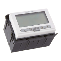
Rimettere il coprimorsetti nella propria
sede I.
Collegamenti elettrici
Collegamento
per attivazione da remoto
Collegamento
per contatto magnetico
CARICO
CARICO
U2
U1
CHIUSO
APERTO
APERTO
 Loading...