28
48
48
28
Page 8 - Manual FA01734-EN - 06/2022 - © CAME S.p.A. - The contents of this manual may be changed, at any time, and without notice. - Translation of the original instructions
Cable type and minimum thicknesses
Connection
Cable length
1 < 10 m
Cable length
10 < 20 m
Cable length
20 < 30 m
Power 230/400V AC
4G x 1,5 mm
2
4G x 1.5 mm
2
4G x 2.5 mm
2
Power 230V AC
3G x 1,5 mm
2
3G x 1.5 mm
2
3G x 2.5 mm
2
Power to motor 230/400V AC
4G x 1,5 mm
2
4G x 1.5 mm
2
4G x 2.5 mm
2
Power to motor 230/400V AC
3G x 1,5 mm
2
3G x 1.5 mm
2
3G x 2.5 mm
2
Power to motor 24V DC
2G x 1,5 mm
2
2G x 1.5 mm
2
2G x 2.5 mm
2
Flashing light
2 x 1,5 mm
2
2 x 1.5 mm
2
2 x 1.5 mm
2
Left Photocells
2 x 0,5 mm
2
2 x 0.5 mm
2
2 x 0.5 mm
2
Right Photocells
4 x 0,5 mm
2
4 x 0.5 mm
2
4 x 0.5 mm
2
Power to accessories
2 x 0,5 mm
2
2 x 0.5 mm
2
2 x 1 mm
2
Command buttons
2 x 0,5 mm
2
2 x 0.5 mm
2
2 x 0.5 mm
2
Endstops
3 x 0,5 mm
2
3 x 1 mm
2
3 x 1.5 mm
2
Encoder connection
max. 30 m
Antenna connection
max. 10 m
When operating at 230 V and outdoors, use H05RN-F-type cables that are 60245 IEC 57 (IEC) compliant; when indoors, use H05VV-F-type cables
that are 60227 IEC 53 (IEC) compliant. For power supplies up to 48 V, use cables compliant with standard EN 50267-2-1 (CEI).
To connect the antenna, use RG58 cable (up to 5 m).
If cable lengths di er from those specifi ed in the table, establish the cable sections depending on the actual power draw of the connected
devices and according to the provisions of regulation CEI EN 60204-1.
For multiple, sequential loads along the same line, recalculate the values in the table according to the actual power draw and distances.
For connecting products that are not covered in this manual, please see the documentation accompanying the relevant products.
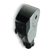
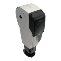
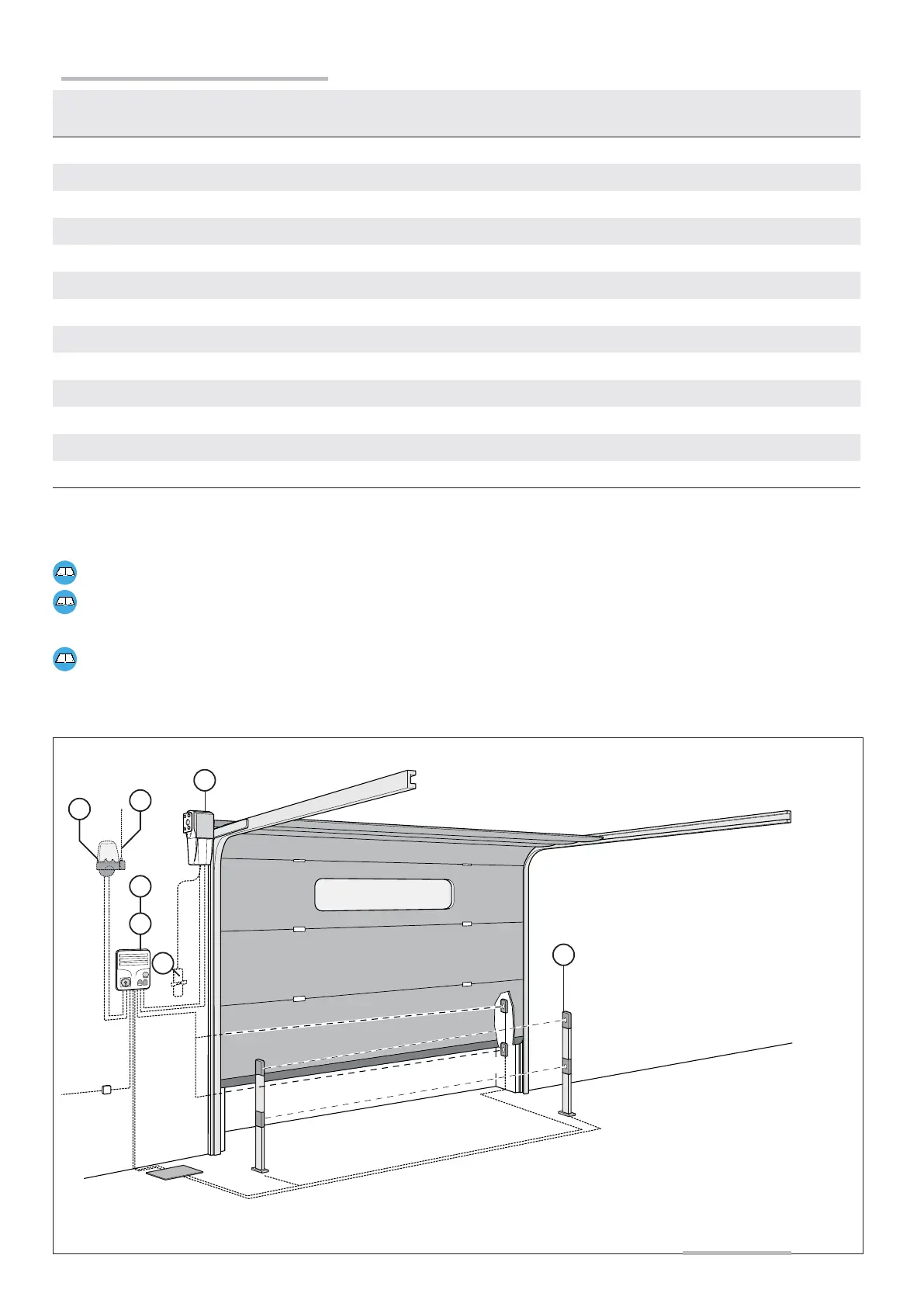
① Gearmotor
② Control panel with buttons
③ Radio receiver
④ Flashing light
⑤ Antenna
⑥ Safety photocell
⑦Motor release
Installing the operator
on large and regular
sectional doors
 Loading...