CAT - 24
DocumentazioneDocumentazione
DocumentazioneDocumentazione
Documentazione
TecnicaTecnica
TecnicaTecnica
Tecnica
M47
rev. rev.
rev. rev.
rev. 1.0
©
CAME 01/98 CAME 01/98
CAME 01/98 CAME 01/98
CAME 01/98
119GM47119GM47
119GM47119GM47
119GM47
SERIESERIE
SERIESERIE
SERIE
CATCAT
CATCAT
CAT
| CAT SERIES |
SÉRIESÉRIE
SÉRIESÉRIE
SÉRIE
CATCAT
CATCAT
CAT| BAUREIHE CAT|
SERIESERIE
SERIESERIE
SERIE
CATCAT
CATCAT
CAT
Impianto tipoImpianto tipo
Impianto tipoImpianto tipo
Impianto tipo
1.1.
1.1.
1.
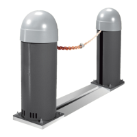
Gruppo CAGruppo CA
Gruppo CAGruppo CA
Gruppo CA
TT
TT
T
--
--
-
XX
XX
X
2.2.
2.2.
2.
Gruppo CAGruppo CA
Gruppo CAGruppo CA
Gruppo CA
TT
TT
T
-I-I
-I-I
-I
3.3.
3.3.
3.
Ricevitore radioRicevitore radio
Ricevitore radioRicevitore radio
Ricevitore radio
4.4.
4.4.
4.
Catena "Genovese"Catena "Genovese"
Catena "Genovese"Catena "Genovese"
Catena "Genovese"
5.5.
5.5.
5.
Guida protezione catenaGuida protezione catena
Guida protezione catenaGuida protezione catena
Guida protezione catena
a pavimentoa pavimento
a pavimentoa pavimento
a pavimento
6.6.
6.6.
6.
Colonnina per lettoreColonnina per lettore
Colonnina per lettoreColonnina per lettore
Colonnina per lettore
magneticomagnetico
magneticomagnetico
magnetico
7.7.
7.7.
7.
LL
LL
L
ettore magneticoettore magnetico
ettore magneticoettore magnetico
ettore magnetico
8.8.
8.8.
8.
Spira di rilevamentoSpira di rilevamento
Spira di rilevamentoSpira di rilevamento
Spira di rilevamento
magneticomagnetico
magneticomagnetico
magnetico
9.9.
9.9.
9.
FF
FF
F
otocellula di sicurezzaotocellula di sicurezza
otocellula di sicurezzaotocellula di sicurezza
otocellula di sicurezza
10.10.
10.10.
10.
Colonnina per fotocellulaColonnina per fotocellula
Colonnina per fotocellulaColonnina per fotocellula
Colonnina per fotocellula
11.11.
11.11.
11.
LL
LL
L
ampeggiatore diampeggiatore di
ampeggiatore diampeggiatore di
ampeggiatore di
movomentomovomento
movomentomovomento
movomento
12. Antenna12. Antenna
12. Antenna12. Antenna
12. Antenna
Standard installation
1. CAT-X unit
2. CAT-I unit
3. Radio receiver
4. "Genovese" chain
5. Floor-level chain protection
ramp
6. Column for magnetic card
reading unit
7. Magnetic card reading unit
8. Magnetic detector loop
9. Photocell
10. Column for photocell
11. Flashing light
12. Antenna
Installation typeInstallation type
Installation typeInstallation type
Installation type
1.1.
1.1.
1.
Groupe CAGroupe CA
Groupe CAGroupe CA
Groupe CA
TT
TT
T
--
--
-
XX
XX
X
2.2.
2.2.
2.
Groupe CAGroupe CA
Groupe CAGroupe CA
Groupe CA
TT
TT
T
-I-I
-I-I
-I
3.3.
3.3.
3.
RR
RR
R
eceveur radioeceveur radio
eceveur radioeceveur radio
eceveur radio
4.4.
4.4.
4.
Chaîne "Genovese"Chaîne "Genovese"
Chaîne "Genovese"Chaîne "Genovese"
Chaîne "Genovese"
5.5.
5.5.
5.
Guide protection de laGuide protection de la
Guide protection de laGuide protection de la
Guide protection de la
chaîne au solchaîne au sol
chaîne au solchaîne au sol
chaîne au sol
6.6.
6.6.
6.
Colonne pour le lecteurColonne pour le lecteur
Colonne pour le lecteurColonne pour le lecteur
Colonne pour le lecteur
magnétiquemagnétique
magnétiquemagnétique
magnétique
7.7.
7.7.
7.
LL
LL
L
ecteur magnétiqueecteur magnétique
ecteur magnétiqueecteur magnétique
ecteur magnétique
8.8.
8.8.
8.
Spire de relévamentSpire de relévament
Spire de relévamentSpire de relévament
Spire de relévament
magnétiquemagnétique
magnétiquemagnétique
magnétique
9.9.
9.9.
9.
PhotocellulePhotocellule
PhotocellulePhotocellule
Photocellule
10.10.
10.10.
10.
Colonne pour leColonne pour le
Colonne pour leColonne pour le
Colonne pour le
photocellulephotocellule
photocellulephotocellule
photocellule
11.11.
11.11.
11.
Clignotant de mouvementClignotant de mouvement
Clignotant de mouvementClignotant de mouvement
Clignotant de mouvement
12.12.
12.12.
12.
AntenneAntenne
AntenneAntenne
Antenne
Standard montage
1
. CAT-X - Bausatz
2. CAT-I - Bausatz
3. Radioempfänger
4. Kette typ "Genovese"
5. Boden-Kettenschutzschiene
6. Magnetschriftlesersäule
7. Magnetschriftleser
8. Magnetische
Aufnahmewindung
9. IR Lichtschranke
10. Photozell-Säule
11. Blinkleuchte
12. Antenne
Instalación tipoInstalación tipo
Instalación tipoInstalación tipo
Instalación tipo
1.1.
1.1.
1.
Grupo CAGrupo CA
Grupo CAGrupo CA
Grupo CA
TT
TT
T
--
--
-
XX
XX
X
2.2.
2.2.
2.
Grupo CAGrupo CA
Grupo CAGrupo CA
Grupo CA
TT
TT
T
-I-I
-I-I
-I
3.3.
3.3.
3.
RR
RR
R
adiorreceptoradiorreceptor
adiorreceptoradiorreceptor
adiorreceptor
4.4.
4.4.
4.
Cadena "Genovese"Cadena "Genovese"
Cadena "Genovese"Cadena "Genovese"
Cadena "Genovese"
5.5.
5.5.
5.
Guia de protecciónGuia de protección
Guia de protecciónGuia de protección
Guia de protección
cadena en el suelocadena en el suelo
cadena en el suelocadena en el suelo
cadena en el suelo
6.6.
6.6.
6.
Columna para lectorColumna para lector
Columna para lectorColumna para lector
Columna para lector
magneticomagnetico
magneticomagnetico
magnetico
7. L7. L
7. L7. L
7. L
ector magneticoector magnetico
ector magneticoector magnetico
ector magnetico
8.8.
8.8.
8.
Espira de detecciónEspira de detección
Espira de detecciónEspira de detección
Espira de detección
magnéticamagnética
magnéticamagnética
magnética
9.9.
9.9.
9.
FF
FF
F
otocélula de seguridadotocélula de seguridad
otocélula de seguridadotocélula de seguridad
otocélula de seguridad
10.10.
10.10.
10.
Columna para fotocélulaColumna para fotocélula
Columna para fotocélulaColumna para fotocélula
Columna para fotocélula
de seguridadde seguridad
de seguridadde seguridad
de seguridad
11.11.
11.11.
11.
Làmpara de movimientoLàmpara de movimiento
Làmpara de movimientoLàmpara de movimiento
Làmpara de movimiento
12.12.
12.12.
12.
AntenaAntena
AntenaAntena
Antena
Barriera a catena per l'accesso carrabile fino a 16 m.Barriera a catena per l'accesso carrabile fino a 16 m.
Barriera a catena per l'accesso carrabile fino a 16 m.Barriera a catena per l'accesso carrabile fino a 16 m.
Barriera a catena per l'accesso carrabile fino a 16 m.
Chain barrier for controlling passageways up to 16 metres wide
Barrière a chaîne pour accès jusqu'à 16 mètresBarrière a chaîne pour accès jusqu'à 16 mètres
Barrière a chaîne pour accès jusqu'à 16 mètresBarrière a chaîne pour accès jusqu'à 16 mètres
Barrière a chaîne pour accès jusqu'à 16 mètres
Kettensperre für maximal 16 m. breite Zu - und Durchfahrten
Barrera de acceso a cadena de hasta 16 metrosBarrera de acceso a cadena de hasta 16 metros
Barrera de acceso a cadena de hasta 16 metrosBarrera de acceso a cadena de hasta 16 metros
Barrera de acceso a cadena de hasta 16 metros
1
2
9
9
9
9
7
6
8
4
3
5
10
12
11
T T RRGG5588
2 2 x x 1 1 - - TTXX2 2 x x 11,,55
2 2 x x 11,,55
4 4 x x 11
2 2 x x 11
2 2 x x 11
4 4 x x 11
2 2 x x 11
33xx11,,55//223300VV