5
V121
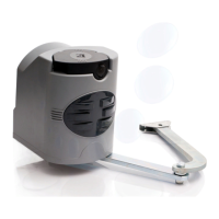
SLIDING LEVER FASTENING
- Centrally x the transmission arm to the door’s upper crosspiece with the rivets provided (or possible screws);
- Move the sliding runner and hook it to the transmission arm after removing the preset screw.
N.B.: if the adapter arm (V201) is used, hook the carriage to the sliding runner.
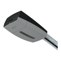
GEARMOTOR INSTALLATION
- Remove the automation container cover by unscrewing the ø3.9x13 screw;
- Fasten the gear motor to the sliding rail’s back terminal in the desired position with the three ø6.3x45 screws provided;
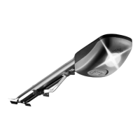
RELEASING THE GEARMOTOR
- Turn the release handle as illustrated; the release will re-hitch automatically at the rst manoeuvre, by returning the lever to its
start position.
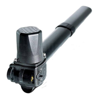
- If there is a V121 cable release device (read the technical documentation accompanying the accessory for assembly instructions),
turn the handle as illustrated to lock and the gearmotor.
Release Engage

 Loading...