Do you have a question about the CAME V900E and is the answer not in the manual?
Outlines essential checks and safety precautions before starting the installation.
Provides an overview of the control panel's functions, power, and safety features.
Identifies and lists all the key components and terminals on the electronic control panel.
Illustrates the power supply and accessory connection points on the control board.
Outlines preparatory steps before programming the door's end-stop positions.
Step-by-step guide for setting the fully closed position of the door.
Step-by-step guide for setting the fully open position of the door.
Provides a troubleshooting guide for common malfunctions and their solutions.
The CAME V900E is an automated kit designed for powering sectional and overhead garage doors in residential and condominium settings. This device is intended for professional installers or qualified persons, emphasizing adherence to installation instructions to prevent damage.
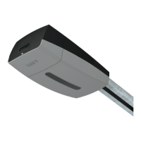
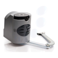
The V900E automation system primarily consists of an engine block, a transmission rail (available with either a belt or chain system), and a transmission arm. The engine block, housed within an ABS container with a courtesy light window, integrates a 24V gearmotor, a control panel, and a transformer. The gearmotor features an aluminum die-cast casing, enclosing an irreversible reduction system with a worm-screw and helical-crown gear, permanently lubricated with fluid grease.
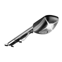
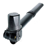
The transmission guide, made of cold-pressed galvanized sheeting, includes a belt/chain tension device at the front end and an ABS support at the other end to hold the gearmotor. A traction slide, which incorporates an emergency release mechanism and a bracket for fastening to the transmission arm, runs inside the transmission guide. The transmission arm itself comes in various sizes and shapes to suit different garage door types.
The control panel, powered by 230V on the L-N terminals, operates at a 50/60 Hz frequency. It can manage accessories up to 40W. The panel also provides a service light that illuminates for 2 minutes and 30 seconds when the door opens. The V900E can be connected to an automation kit with emergency batteries for continued operation during power outages.
The system features amperometric obstruction detection, which adjusts sensitivity during opening, closing, and slow-down phases. If the force exerted by the engine exceeds the adjusted level, the system reverses direction. This detection function can be deactivated using dip-switches. The control panel also includes automatic closing, which can be adjusted for a waiting time between 1 and 120 seconds after opening. Setting the waiting time to minimum disables the automatic closing function.
The V900E supports various warning devices, including a movement flasher (24V-25W max.) that flashes during opening and closing. It also integrates with safety photocells and a safety sensitive profile to enhance user protection.
The V900E is designed for ease of installation and programming, though it requires qualified personnel. Preliminary checks ensure the mounting area is hazard-free, a suitable omnipolar disconnection device is in place, and all connections are properly insulated. The door structure, hinges, and moving parts must be in good working order.
Installation involves fastening the transmission guide to the center of the doorway and ensuring it is horizontal with the ceiling. Angle brackets or tension brackets may be used to secure the guide. The guide arm is fastened to the top of the door frame, perpendicular to the transmission guide. The traction slide is released, moved towards the door, and hooked onto the guide arm.
The gearmotor unit is fastened to the guide's support bracket, and its cover is removed for access. Cable glands are affixed to convey electrical cables.
Programming the end-stops is a critical step. This involves releasing the automation, positioning the door in the fully opened position, and fastening the mechanical stop to the traction slide. The door is then manually closed until the release is locked. To program the closing end-stop, dip-switch n°1 is set to ON, and the AP/CH switch is pressed and held until the door closes. The programming signal LED flashes to indicate the process. For the opening end-stop, the OPEN button is pressed and held until the door is fully open. The ENC/RADIO button is then pressed, and the LED flashes to confirm successful programming. Finally, dip-switch n°1 is set to OFF.
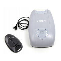
The V900E supports remote control activation. An antenna is connected to the board using an RG58 cable. Various radiofrequency cards (AF130, AF150, AF26, AF30, AF43S/AF43SM, AF43SR, AF40) are compatible, depending on the transmitter series used. Jumpers on the radiofrequency card must be positioned correctly. The radiofrequency card is connected to the electrical board after power is shut off or batteries are disconnected.
Transmitters from TOP, TAM, ATOMO, and TOUCH series can be programmed. For TOP series transmitters, the code is input into the C selector, and the channel is set on D. For QUARZ TOP series, a J coding jumper is inserted, the code is memorized by pressing P1 and/or P2, and the J jumper is then removed. Memorization is confirmed by a double sound. For T264M-T304M and T2622M-T3022M transmitters, the ENC/RADIO button on the circuit board is pressed until the LED flashes, then the transmitter button is pressed to memorize the code, and the LED stays on to confirm.
The V900E unit does not require specific maintenance. However, as a precautionary measure, especially with intensive use, it is recommended to periodically check (every 6 months) the electric wire connected to the motor, the chain and belt tension, the tightness of nuts, and the proper oiling of sliding points between fixed and mobile parts. All checks should be recorded in a dedicated record-book.
The manual provides a problem-solving guide for various malfunctions, including issues with opening/closing, remote control, photocells, and emergency batteries. For example, if the automation does not open or close, checks involve the power supply and line fuses. If the automation opens but does not close, the N.C. (1-2) safety contact should be checked. If the remote control does not work, the obstruction detection function might need deactivation, or the radio code may need to be re-memorized. Issues with force exertion can be resolved by adjusting the A.C.T. trimmer or checking belt/chain tension.
For demolition and disposal, CAME CANCELLI AUTOMATICI S.p.A. adheres to an Environmental Management System certified in compliance with UNI EN ISO 14001. Packaging components (cardboard, plastic) are classified as solid urban waste and can be disposed of through recycling. Product components, including aluminum, plastics, iron, and electrical wires, can be disposed of in normal garbage collection bins or recycled in authorized centers. Electrical boards and remote control batteries, which may contain polluting substances, should be removed and given to qualified service companies for proper disposal. It is advised to check specific regulations in force in the place of disposal.
| Power Supply | 230V AC |
|---|---|
| Motor Type | DC Motor |
| Safety | Yes |
| Remote Control | Yes |
| Battery Backup | No |