Do you have a question about the CAME VER10DMS and is the answer not in the manual?
Identifies the product as automation systems for garage doors.
Crucial safety directives and warnings for installers to ensure a safe installation process.
Essential guidelines for end-users regarding safe operation and potential hazards.
Procedures for environmentally sound dismantling and disposal of the product and its packaging.
Highlights potential hazards and risks associated with moving parts and electricity.
Details product identification, key symbols, model descriptions, and approved applications.
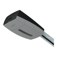
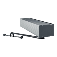
Lists and illustrates the various components of the operator unit.
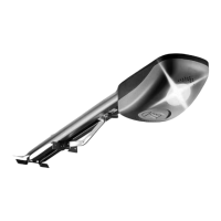
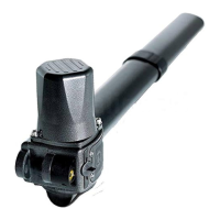
Lists optional accessories not supplied with the main product.
Detailed identification of terminals and components on the main control board.
Physical dimensions and limitations for door compatibility and installation.
Recommended fuse ratings and comprehensive technical specifications for the operator.
Guidelines on appropriate cable types and minimum thicknesses for electrical connections.
Steps for preparing and correctly mounting the guide rail for the operator.
Procedure for securely attaching the guide rail to the ceiling or support structure.
Steps for mounting the operator unit onto the prepared guide rail.
Steps for preparing the operator for electrical cable connections.
Securing the transmission arm to the operator's slide mechanism.
Instructions for routing and protecting electrical cables for safe operation.
Details on connecting the operator to mains power and accessory outputs.
Table detailing the maximum output power for connected accessories and devices.
Connecting various control devices like STOP buttons, keypads, and readers.
Connecting transponder selectors and antennas for wireless control.
Configuring additional lights and flashing beacons to indicate operator status.
Wiring and connection for safety photocells and sensitive edges.
Wiring diagrams for DELTA-S, DXR/DLX photocells, and DFWN sensitive edges.
Illustrations showing the final steps of closing the operator housing.
Explanation of the ESC, <>, and ENTER buttons for navigating the programming menu.
Initial steps and considerations before commencing the programming process.
Introduction to the functions menu and the 'Total stop' function.
Mapping functions to CX and CY inputs for safety devices.
Testing safety devices and configuring hold-to-run operation.
Configuring commands 2-7, 2-3P, and obstacle handling.
Configuring warning lights, automatic closure, and related timers.
Adjusting soft start, closing thrust, and selecting sensor types.
Fine-tuning opening/closing speeds, slowdowns, and obstruction sensitivity.
Adjusting partial opening percentage and slowdown parameters.
Settings for RSE communication, data import/export, and CRP addressing.
Mapping functions to wireless safety devices for RIO T1/T2 systems.
Adding/removing users and selecting radio decoding methods.
Adjusting motor force, performing tests, and resetting parameters.
Viewing manoeuvre counts and adjusting motor torque.
Displaying firmware version and managing data via memory roll.
Errors related to calibration, encoder function, and service tests.
Errors indicating obstacles, serial, or wireless communication failures.
Errors related to incompatible transmitters or unconfigured wireless systems.
| Maximum Thrust | 1000 N |
|---|---|
| Motor Voltage | 24 V DC |
| Installation Type | Ceiling mounted |
| Warranty | 2 years |
| Power Supply | 230 V AC |
| Motor Type | DC |
| Safety Features | Obstacle detection |
| Remote Control | Yes |
| Control Options | Remote |
| Noise Level | 60 dB |