Documentazione
Tecnica
T13
rev. 0.4
11/2003
©
CAME
CANCELLI
AUTOMATICI
319T13
ZL22
CANCELLI AUTOMATICI
QUADRO COMANDO
CONTROL PANEL
CUADRO DE MANDO
SERIE Z |
Z SERIES |
SERIE Z
Descrizione quadro comando
Progettato e costruito interamente dalla
CAME Cancelli Automatici S.p.A., risponde
alle vigenti norme di sicurezza.
Quadro elettrico per
motoriduttori serie
UNIPARK
in corrente continua 24V.
Alimentato a 230V (a.c.) con frequenza 50/
60 Hz sui morsetti L1-L2, protetto in
ingresso con un fusibile di linea da 5A.
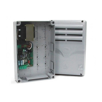
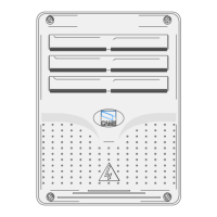
Contenitore in ABS completo di trasforma-
tore, dotata di presa per il riciclo d'aria con
grado di protezione IP54.
Garantito 24 mesi salvo manomissioni.
I dispositivi di comando sono a bassa
tensione e protetti con fusibile da 315mA.
La potenza complessiva degli accessori a
24V protetti da un fusibile a 3.15A, non
deve superare i 60W.
Logica di comando, sicurezza e
accessori collegabili
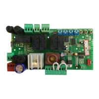
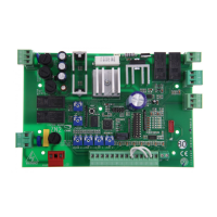
La centralina è dotata di:
- finecorsa di apertura e chiusura elettrici,
ottenuti con sistema amperometrico;
- trimmer che regola la sensibilità della
forza sviluppata del motore;
- predisposizione per l’inserimento del
ricevitore radio per comando a distanza;
- possibilità di comandare fino a 4 motori
(l’installazione di più motori si ottiene,
inserendo la scheda
LM22
per ogni
motore).
CARATTERISTICHE GENERALI
Italiano