EasyManua.ls Logo

CAME ZA3 User Manual

CAME ZA3
12 pages
To Next Page IconTo Next Page
Page #1 background imageLoading...
Page #1 background image
ZA3
Documentazione
Tecnica
S13
rev. 3.1
07/2004
©
CAME
CANCELLI
AUTOMATICI
CANCELLI AUTOMATICI
SERIE Z |
Z SERIES
| SERIE Z
SCHEDA COMANDO
CONTROL BOARD
TARJETA DE MANDO
319S13-1
ITALIANO/ENGLISH/ESPAÑOL
ITALIANO—ENGLISH—ESPAÑOL
QUADRO COM AND O
FUSIBILI
LINEA 5A
ZA3
CH1
AF
FUSIBILE
CENTRALINA
3,15 A
T.L. T.C.A. TR2M.
2
134567
8910
O
N
CH2
DESCRIPTION OF CONTROL BOARD
The ZA3 electric board is suitable for
controlling the automation of ATI, FERNI,
KRONO, FAST and FROG series 230V
swing gates with up to 600W power and
50-60Hz frequency. Wholly designed
and built by CAME Cancelli Automatici
S.p.A.
The board is inserted and fixed to the
ABS case (S4339 o S4340), which has
an IP54 protection level, with air
recycling inlet and transformer.
The board requires 230V (a.c.) at
terminal blocks L1-L2 and the inlet is
protected with two 5A fuses. A 3.15A
fuse protects the low voltage command
devices.
I he accessories’ total wattage to 24V
must not exceed 20W.
DESCRIPCIÓN TARJETA DE MANDO
La tarjeta eléctrica ZA3 es adecuada
para el accionamiento de automa-
tizaciones para puertas de batiente de
la serie ATI, FERNI, KRONO, FAST y
FROG, alimentadas a 230V, con poten-
cia de hasta 600W, frecuencia 50÷60
Hz.
Diseñada y fabricada completamen-
te por CAME Cancelli Automatici
S.p.A.. La tarjeta se instala y fija en
una caja de ABS (S4339 o S4340) con
grado de protección IP54, con toma
para recirculación de aire y transfor-
mador.
La tarjeta se alimenta con tensión a
230V (c.a.) en los bornes L1-L2 y está
protegida en entrada con dos fusibles
de línea de 5A. Los dispositivos de
mando son de baja tensión y están
protegidos con fusible de 3.15A.
La potencia total de los accesorios
de 24V no debe superar los 20W.
CARATTERISTICHE GENERALI
GENERAL CHARACTERISTICS
CARACTERISTICAS GENERALES
DESCRIZIONE SCHEDA COMANDO
La scheda elettrica ZA3 è adatta al
comando di automazioni per cancelli
a battente della serie ATI, FERNI,
KRONO, FAST e FROG, alimentati a
230V con potenza fino a 600W,
frequenza 50÷60 Hz. Progettata e
costruita interamente dalla CAME
Cancelli Automatici S.p.A.
La scheda va inserita e fissata nel
contenitore in ABS (S4339 o S4340)
con grado di protezione IP54, dotato
di presa per il riciclo d’aria e
completo di trasformatore.
La scheda va alimentata con
tensione di 230V (a.c.) sui morsetti
L1-L2 e protetta in ingresso con due
fusibili di linea da 5A. I dispositivi di
comando sono a bassa tensione e
protetti con fusibile da 3.15A.
La potenza complessiva degli
accessori a 24V non deve superare
i 20W.
ENGLISH
ESPANOL
ITALIANO
Question and Answer IconNeed help?

Do you have a question about the CAME ZA3 and is the answer not in the manual?

CAME ZA3 Specifications

General IconGeneral
Operating temperature-20°C to +55°C
Protection ratingIP54
Absorbed power in stand-by5 W
Power supply230 V AC
Motor power supply230 V AC

Summary

General Characteristics of the ZA3 Control Board

Italian Description

Detailed description of the ZA3 control board in Italian.

English Description

Detailed description of the ZA3 control board in English.

Spanish Description

Detailed description of the ZA3 control board in Spanish.

Safety Features and Accessories

Photocell Connections for Safety

Details on photocell connections for gate safety functions.

Connectable Accessories

List of accessories that can be connected to the unit.

Other Available Functions

Additional functions provided by the control board.

Additional Safety and Adjustments

Obstacle Detection and Hammer Movement

Safety features for obstacle detection and hammer movement.

Adjustment Settings

Parameters for automatic closure, opening delay, and operating time.

Main Components Identification

Terminal Blocks and Fuses

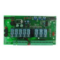
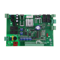
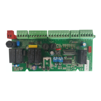
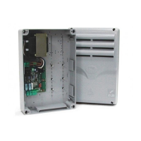
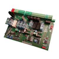
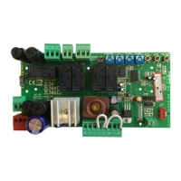
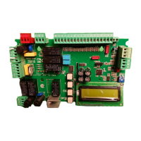
Identification of terminal blocks, line fuses, and control unit fuse.

Indicators, Buttons, and Trimmers

Overview of status LEDs, radio code buttons, and adjustment trimmers.

Sockets and Limiters

Locations for radio frequency board, signal LED, and motor torque limiter.

DIP-Switch Function Configuration

Automatic Closure and Opening Modes

Configuring automatic closure and various opening modes via DIP-Switches.

Obstacle Detection and Maintained Action

Setting obstacle detection and maintained action functions with DIP-Switches.

Re-closure and Partial Stop Functions

Selecting re-closure during opening and partial stop via DIP-Switches.

Electrical Connections Diagram

Power Supply and Motor Wiring

Diagrams for control unit power supply and motor connections.

230V Outputs and Lamps

Wiring for 230V outputs and cycle lamps.

24V Accessories and Signal Lamps

Connections for 24V accessories and gate-opened signal lamp.

Electric Lock and Stop Button Wiring

Wiring for the electric lock and NC stop button.

Transmitter Encoding Procedures

ATOMO Transmitter Encoding

Procedure for encoding ATOMO transmitters.

TOP Transmitter Encoding

Instructions for encoding TOP transmitters.

TAM and TFM Transmitter Encoding

Encoding instructions for TAM and TFM transmitters.

Code Storage and Transmitter Functions

Memory Storage Procedure

Procedure for storing transmitter codes on the base card.

CH1 Function Channel

Direct control channel for motor unit functions.

CH2 Accessory Channel

Direct control channel for accessory devices.

Manufacturer's Declaration

Italian Declaration

Manufacturer's declaration in Italian regarding directives and harmonized standards.

English Declaration

Manufacturer's declaration in English regarding directives and harmonized standards.

Spanish Declaration

Manufacturer's declaration in Spanish regarding directives and harmonized standards.

Related product manuals