EasyManua.ls Logo

CAME ZE4 - User Manual

CAME ZE4
24 pages
Print Icon
To Next Page IconTo Next Page
Loading...
-1-
Documentazione
Tecnica
S35
rev. 3.1
02/2001
©
CAME
CANCELLI
AUTOMATICI
319S35
SCHEDA COMANDO
CONTROL BOARD
CARTE DE COMMANDE
STEUERPLATINE
TARJETA DE MANDO
SERIE Z |
Z SERIES
/ SÉRIE Z |
BAUREIHE Z |
SERIE Z
ZE4
CANCELLI AUTOMATICI
CARATTERISTICHE GENERALI
Descrizione quadro
Il quadro elettrico ZE4 è adatto al
comando di automazioni per porte
basculanti della serie EMEGA, alimentati
a 230V con potenza fino a 600W, fre-
quenza 50÷60Hz.
Progettato e costruito interamente dalla
CAME S.p.A., risponde alle vigenti
norme UNI 8612. Contenitore in ABS
con grado di protezione IP54, dotato di
presa per il riciclo d’aria e completo di
trasformatore.
Il circuito va alimentato con tensione di
230V (a.c.) nei morsetti L1-L2 e protetto
in ingresso con due fusibili da 5A,
mentre i dispositivi di comando a bassa
tensione sono protetti con fusibile da
2A.
La potenza complessiva degli accesso-
ri (24V) non deve superare i 20W.
Il quadro include la funzione di spunto
manovra. Questa funzione si attiva in
fase d’inizio apertura e chiusura del
portone.
Sicurezza
Le fotocellule possono essere collegate
e predisposte per:
-
Riapertura
in fase di chiusura (2-C1),
le fotocellule rilevando un ostacolo
durante la fase di chiusura della porta,
provocano l'inversione di marcia fino
alla completa apertura;
-
Stop totale
(1-2), arresto della porta
con l'esclusione del ciclo di chiusura
automatica, per riprendere il movimen-
to, agire sulla pulsantiera o sul radio-
comando;
Nota: Se un contatto di sicurezza
ITALIANO
Question and Answer IconNeed help?

Do you have a question about the CAME ZE4 and is the answer not in the manual?

CAME ZE4 Specifications

General IconGeneral
BrandCAME
ModelZE4
CategoryControl Unit
LanguageEnglish

Summary

Control Panel Description and Safety

Control Panel Description

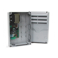
General information about the ZE4 control panel and its purpose.

Safety Features

Details on safety features like photocells and obstacle detection.

Connectable Accessories

List of compatible accessories such as courtesy lights and electric locks.

Other Functions and Adjustments

Other Functions

Explains functions like automatic closing, operator present, limit switch opening, pre-flashing.

Type of Command

Describes different command types like open-stop-close-stop.

Adjustments

Information on adjusting operating time and automatic closing time.

Main Components

Component Identification

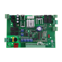
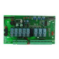
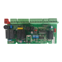
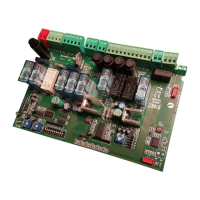
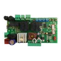
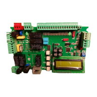
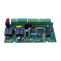
Lists and describes the main components of the control panel.

Electrical Connections

Power, Motor, and Accessory Connections

Wiring diagrams for connecting power supply, motor, and accessories.

Dip-Switch Settings

Function Selection Guide

Guide to selecting functions using dip-switches for various operations.

Adjustments and Torque Limiter

Trimmer Adjustments

Instructions for adjusting operating time and automatic closing time.

Motor Torque Limiter

Guide to adjusting motor torque using faston positions.

Assembly Instructions

Housing and Hinge Installation

Steps for assembling the control panel housing and its hinges.

Radio Control Installation

AF Card Insertion

Procedure for inserting the AF radiofrequency card.

Transmitter Encoding

Transmitter Types and Settings

Instructions for encoding various transmitter types like ATOMO, TOP, TAM.

Code Storage

Storing Transmitter Codes

Procedure for storing transmitter codes using the PROG key and LED.

Related product manuals