9
3-1. Required Tools (Toolkit Part No. 0288-1032B)
Tool Purpose
Pointer puller Pointer removal
Small screwdriver Calibration adjustments
Medium screwdriver Bezel removal/DPU bracket screws
1/8” Open-end wrench Calibration adjustments
1/8 Hex Allen wrench Switch setpoint adjustment
3-2. DPU Installation/Test/Calibration/Maintenance
Refer to the Barton Model 199 DPU user manual (Part No. 10030).
3-3. Bezel/Lens (or Cover) Installation and Removal
WARNING
(EXPLOSIONPROOF UNITS)
PRIOR TO LOOSENING ANY ATTACHING HARDWARE, HOUSING BOLTS, OR
COVER ASSEMBLY, ASSURE SURROUNDING AREA IS, AND REMAINS, WELL
VENTILATED.
PRIOR TO LOOSENING OR REMOVAL CASE/COVER ASSEMBLY, ALL
ELECTRICAL POWER SUPPLIES MUST BE TURNED OFF.
THE COVER MUST BE REMOVED TO CALIBRATE THE INSTRUMENT.
BEFORE ANY MAINTENANCE/CALIBRATION, REVIEW MODEL 199 DPU
MANUAL (Part No. 10030).
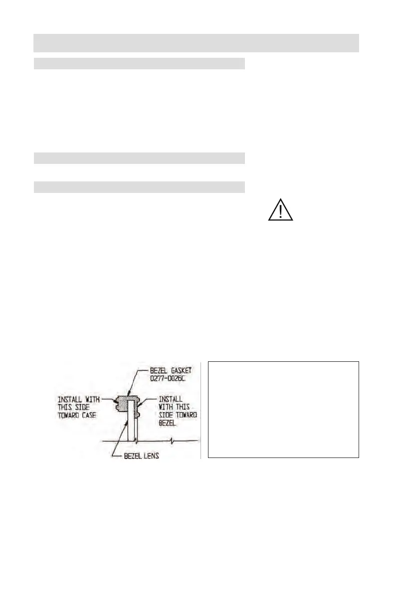
For non-explosionproof units, the bezel gasket (Part No. 0277-0026C) must be
installed as shown below:
The two snubbers (Part No. 0266-0028C) on the scaleplate should not be com-
pressed against the lens cover and the pointer should not touch the lens.
Note—Ensure correct bezel gasket orientation before placing instrument back in
service. Incorrect bezel gasket orientation will cause the instrument indicator to
jam, resulting in inaccurate readings.
SECTION 3 - MAINTENANCE AND CALIBRATION
To remove the bezel and cover lens
on non-explosionproof units:
1. Loosen three screws on the
front of bezel.
2. Tilt out bottom of bezel and
slide bezel upward.
Figure 3-1.
Bezel/Lens