13
Model 752 and 752A Differential Pressure Transmitter Section 3
Section 3—Installation, Startup, and Shutdown
Overview
This section describes the steps required to install the instrument so that it
will perform to its original factory calibration condition. Installation tasks
include
• initial calibration check
• mounting the transmitter
• installing piping
• installing eld wiring
Unpacking/Inspection
The instrument should be inspected at the time of unpacking to detect any
damage that may have occurred during shipment.
IMPORTANT: The unit was checked for accuracy at the factory. Do not change any of
the settings during examination or accuracy will be affected.
The transmitter is shipped in a polyethylene bag to protect the instrument
from contamination. Remove this bag only in a clean area.
Initial Calibration Check
The Model 752 and 752A transmitters are factory-calibrated. However, to
ensure that the calibration is intact following shipping, a calibration check
is recommended prior to operating the instrument. See Calibration, page 19,
for step-by-step instructions. Record the "as found" values and recalibrate, if
necessary.
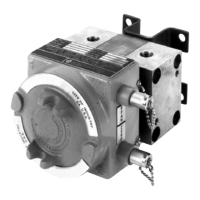
Mounting
Mount the transmitter so that the pressure housings are in a horizontal posi-
tion and when the operator is facing the transmitter cover, the controls are on
the right side. Use mounting structures that are designed to minimize vibra-
tion and avoid resonance and/or keep resulting amplication below 33 Hz.
Support connected process tubing and conduit using the same mounting as the
instrument base to minimize relative motion of the instrument and connec-
tions.
Wall or Rack Mounting
1. Locate and drill four bracket mounting holes in the mounting surface.
2. Attach the instrument to the wall using 5/16" (8 mm) bolts, Grade 5 or
better, and torque to 10-20 ft-lb.