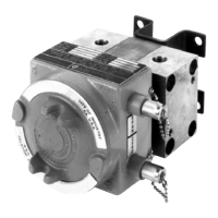
EasyManua.ls Logo

Cameron BARTON 764 User Manual

Default Icon
36 pages
To Next Page IconTo Next Page
Page #1 background imageLoading...
Page #1 background image
BARTON
®
MODEL 764
DIFFERENTIAL PRESSURE
TRANSMITTER
User Manual
Part No. 9A-C10880, Rev. 05
January 2020
Contents
Section 1—Introduction ................................................................................. 5
General ......................................................................................................... 5
Product Description....................................................................................... 5
Di󰀨erential Pressure Unit (DPU) ............................................................... 5
Electronic Transmitter................................................................................ 5
Power Supply ............................................................................................ 5
Specications ................................................................................................ 6
Performance .............................................................................................. 6
Application ................................................................................................. 7
Storage: ..................................................................................................... 8
Section 2—Theory of Operation .................................................................... 9
Basic Components ........................................................................................ 9
Di󰀨erential Pressure Unit (DPU) ............................................................... 9
Draining or Venting.....................................................................................9
Temperature Compensation......................................................................10
Bellows......................................................................................................10
Strain Gage Assembly...............................................................................10
Range Springs..........................................................................................10
Electronic Transmitter...............................................................................10
Basic Operation ...........................................................................................11
Reverse Polarity Protection ......................................................................11
Regulator ................................................................................................. 12
Strain Gage Bridge Network.................................................................... 12
Signal Amplier........................................................................................ 12
Current Amplier...................................................................................... 12
Temperature Compensation........................................................................ 12
Section 3—Installation and Operation ........................................................ 13
Unpacking/Inspection.................................................................................. 13
Pre-Operating Instructions .......................................................................... 13
Mounting ..................................................................................................... 13

Questions and Answers:

Cameron BARTON 764 Specifications

General IconGeneral
ModelBARTON 764
CategoryTransmitter
ManufacturerCameron
Output Signal4-20 mA
Enclosure RatingNEMA 4X, IP66
Accuracy±0.1% of span
Wetted Materials316 Stainless Steel
Operating Temperature-40 to 85°C (-40 to 185°F)
Process Connection1/4" NPT

Summary

Section 1: Introduction

General Information

Overview of the Model 764 Differential Pressure Transmitter's function and design.

Product Description

Details the combined DPU and electronic circuit of the transmitter.

Key Components

Details the Differential Pressure Unit (DPU) and Electronic Transmitter.

Power Supply Requirements

Specifies the need for a regulated DC power supply.

Section 1: Performance Specifications

Performance Specifications

Comprehensive performance metrics including range, accuracy, and sensitivity.

Adjustability and Control Features

Covers field adjustments for span and zero suppression.

Operational Effects and Noise

Details load effect, power supply effect, noise, and suppression.

Environmental Performance Ratings

Thermal, radiation, and seismic performance.

Section 1: Specialized Conditions

Specialized Performance Conditions

LOCA performance, long-term drift, and time response.

Pressure and Connection Details

Max safe pressure, static/overpressure effects, and process connections.

Application and Service Life

Suitability for harsh environments and qualified service life.

Section 1: Environmental and Storage

Design Basis Event (DBE) Environment

Specifies conditions for Design Basis Events and severe environments.

Storage Guidelines

Instructions for storing the transmitter to maintain service life.

Section 2: Theory of Operation

Basic Components Overview

Introduces the fundamental parts of the transmitter.

Differential Pressure Unit (DPU) Function

Details the DPU's mechanism, components, and draining/venting.

Temperature Compensation Mechanism

Describes how ambient temperature effects are compensated.

Section 2: Transmitter Operation

Bellows and Strain Gage Assembly

Details bellows construction and the strain gage sensor mechanism.

Range Springs and Electronic Transmitter

Explains range springs and the electronic signal conversion.

Section 2: Transmitter Electronics

Basic Operational Flow Diagram

Explains the overall current flow and stages in the transmitter.

Polarity Protection Circuit

Details the protection against reversed input polarity.

Section 2: Internal Circuitry

Electronic Transmitter Circuit Stages

Describes the Regulator, Bridge Network, Signal, and Current Amplifiers.

Factory Temperature Compensation

Notes that temperature compensation is performed at the factory.

Section 3: Installation and Operation

Unpacking and Initial Inspection

Steps for receiving and inspecting the instrument for damage.

Pre-Operation Verification Steps

Essential checks before initial startup and calibration.

Transmitter Mounting Procedures

Instructions for physically mounting the transmitter securely.

Vibration Minimization Guidelines

Guidance on mounting to reduce vibration effects.

Section 3: Piping and Connections

Piping Installation Best Practices

Recommended practices for instrument piping.

Process Connections and Considerations

Guidance on distance, slope, temperature, pulsation, and leakage.

High-Pressure Connection and Manifolding

How to connect high-pressure side and use manifolds.

Section 3: Electrical Installation

Electrical Wiring Connections

Details on field wiring connections and important warnings.

Section 3: Loop Resistance

Loop Resistance Calculations Method

Method to calculate total loop resistance values for proper operation.

Section 3: Loop Resistance Examples

Loop Resistance Calculation Examples

Provides examples for calculating loop resistance under various conditions.

Section 3: EMI/RFI Shielding

EMI/RFI Shielding Precautions

Recommended precautions to limit electromagnetic interference.

Section 3: Calibration Procedures

Initial Transmitter Calibration Procedure

Steps for calibrating the transmitter after installation.

Calibration Verification Procedure

Steps to check and verify the transmitter's calibration accuracy.

Section 3: Calibration Checkpoints

Calibration Checkpoints and Output Values

Table of expected output values for calibration at various pressure points.

Section 3: Startup and Shutdown

Transmitter Startup Procedure

Step-by-step instructions for operating the transmitter.

Transmitter Shutdown Procedure

Step-by-step instructions for safely shutting down the transmitter.

Section 4: Maintenance Overview

General Maintenance Overview

Overview of maintenance and authorized field repairs.

DPU Inspection and Cleaning Process

Procedures for inspecting and cleaning the DPU, including safety checks.

Section 4: DPU Maintenance and Calibration

DPU Reassembly and Lubrication

O-ring replacement, housing reinstallation, and lubrication.

Periodic Calibration Requirements

Guidelines for performing periodic transmitter calibration.

Calibration Equipment Checklist

Lists the required equipment for calibration.

Section 4: Periodic Calibration

Periodic Calibration Procedure

Step-by-step process for performing periodic transmitter calibration.

Calibration Checkpoints Table

Table of expected output values for calibration at various pressure points.

Section 4: Transmitter Cover Maintenance

Transmitter Cover Removal Procedure

Steps for safely removing the transmitter cover.

Transmitter Cover Reinstallation Procedure

Steps for correctly reinstalling the transmitter cover.

Section 4: Connector Operation

EGS Quick Disconnect Connector Operation

How to secure and disconnect the EGS connector assembly.

Section 4: Connector Replacement

Lead Wire and Connector Replacement

Information on replacing lead wires and connector assemblies.

EGS Connector Removal Process

Steps required to remove the EGS Quick Disconnect connector.

EGS Connector Installation Process

Steps required to install the EGS Quick Disconnect connector.

Section 4: EGS Connector Completion

EGS Connector Installation Completion

Final steps for installing the EGS Quick Disconnect connector.

Section 4: Barton Connector Replacement

Barton Style Connector Removal

Steps to remove the Barton style connector assembly.

Barton Style Connector Installation

Steps to install the Barton style connector assembly.

Section 4: Troubleshooting

Troubleshooting Common Issues

Table of problems, probable causes, and corrective actions.

Section 5: Assembly and Parts

Model 764 Assembly Diagram

Exploded view showing the assembly of the transmitter.

Section 5: Parts and Torque

Replacement Parts List

Detailed list of available replacement parts and part numbers.

Recommended Torque Values

Table specifying torque values for installation hardware.

Section 6: Dimensional Drawings

Transmitter Front View Dimensions

Technical drawing showing front view dimensions.

Transmitter Rear View Dimensions

Technical drawing showing rear view dimensions.

Transmitter Side View Dimensions

Technical drawing showing side view dimensions.

Section 6: Warranty and Brand

Product Warranty Information

Details of the manufacturer's warranty terms and conditions.

Product Brand Trademark

Information about the registered trademark "Barton".

Related product manuals