11
Model 764 Differential Pressure Transmitter Section 2
compression decreases in resistance. The two gages are connected to form
two active arms of a bridge circuit. The bridge output signal is conditioned
and converted to a 4-20 mA or 10-50 mA output signal by the transmitter
electronics.
Basic Operation
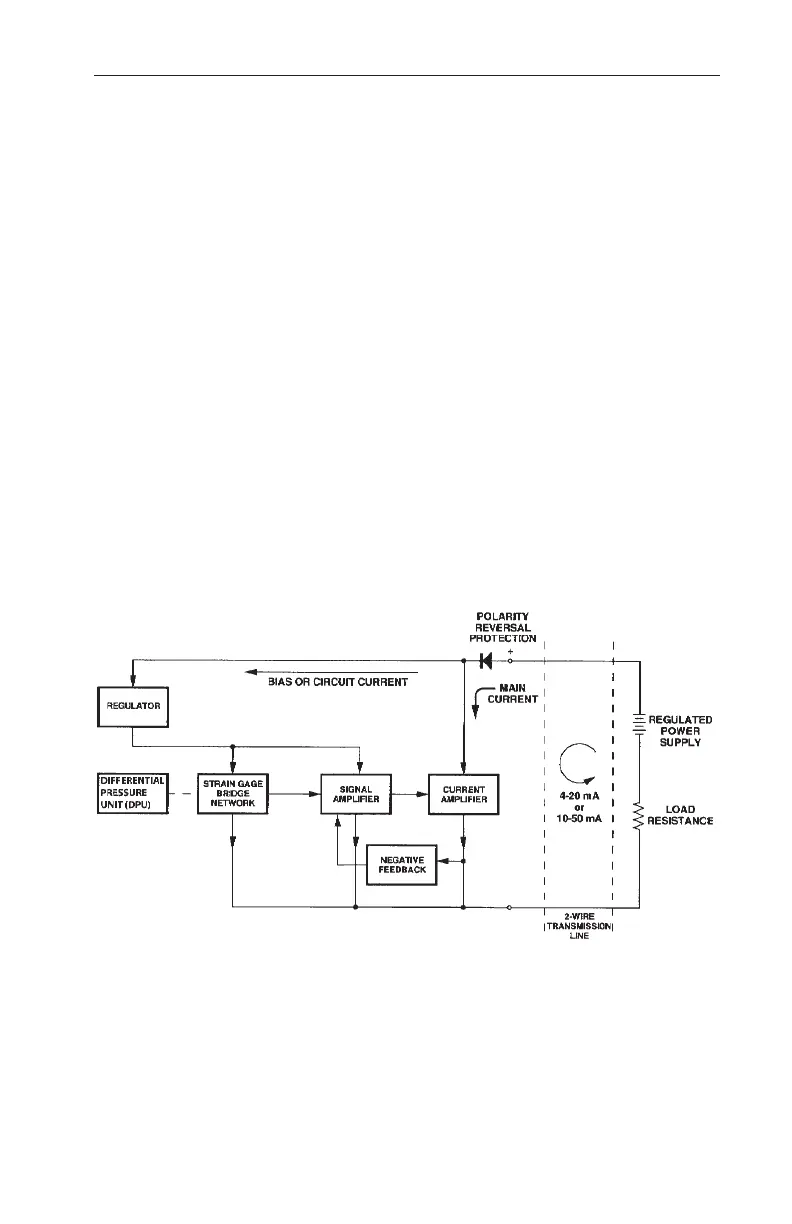
The electronic transmitter is basically a loop current regulating device, where
loop current is controlled by an input of mechanical force or motion. The
block diagram (Figure 2.3) shows the relationships of the various stages and
the main ow of the electrical currents. As shown, the transmitter, power sup-
ply, and load (line plus receiving device) are connected in series.
The current from the power supply enters the transmitter, passes through the
reverse polarity protecting diode, then divides into two separate paths. The
main current ows through the current amplier stage and returns to the loop.
The remainder of the current passes through the electronic regulator where it
divides into two paths, through the bridge circuit and the signal amplier. The
current is then returned to the loop. The total loop current ows through the
load and back to the power supply.
Figure 2.3—Operational block diagram
Reverse Polarity Protection
Reverse input polarity protection is provided by the forward-conducting
diode. In the event the polarity of the input is reversed, the diode blocks the
input and prevents the reversed input power from damaging the electronic
circuit components.