16
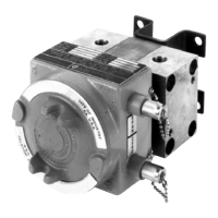
Section 3 Model 764 Differential Pressure Transmitter
Minimum resistance is based upon maximum transmitter power dissipation
(Watts) at the maximum design temperature conditions, and qualied life limited
by heat rise. For proper operation at post-accident conditions, this minimum
resistance must exist.
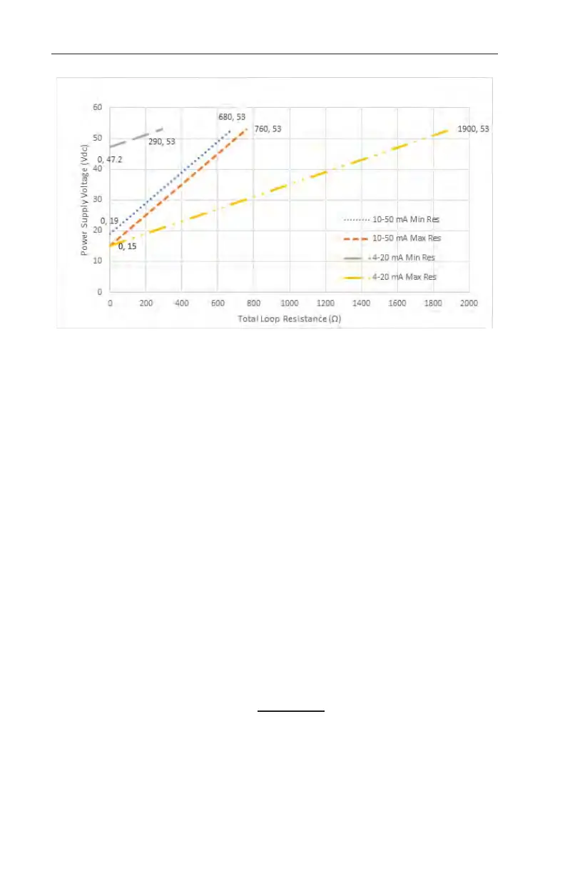
Figure 3.2—Power supply and loop resistance
Load and Line Resistance Calculations
Use the following method to calculate values of load and line resistance:
Total Loop Resistance (R
T
) = R
Line
+ R
Load
+
R
Ext
Power Supply Voltage = V
DC
(53 V max. for 4-20 mA or 10-50 mA Systems)
Minimum no load Transmitter Voltage = T
VDC
(15 V for both 4-20 mA and
10-50 mA Systems)
Maximum no load Transmitter Voltage = T
VDC
(47.2 V for 4-20 mA and 19 V
for 10-50 mA Systems)
Transmitter Current = I
DC
(20 mA or 50mA)
R
T =
T
VDC -
T
VDC
I
DC
Example 1 : (Maximum loop resistance for 10-50 mA system):
V
DC
= 53 Vdc
T
VDC
= 15 Vdc
I
DC
= 50 mA R
T
= (53-15) / 0.05 = 760 Ohms