14
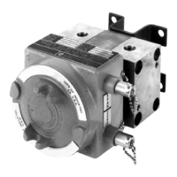
Section 3 Model 764 Differential Pressure Transmitter
Piping
The practices described in this section should be followed for all instrument
piping.
Distance
The distance between the primary device and the instrument should be as
short as possible.
Slope
Slope all piping at least one inch per linear foot to prevent liquid or gas en-
trapment in the lines or the instrument.
• Slope all piping downward from the transmitter when used in gas instal-
lations to prevent liquid entrapment.
• Slope all piping upward from the transmitter when used in liquid applica-
tions to prevent gas entrapment.
Process Temperature
If the process temperature exceeds 135°F, provide a minimum of 1-foot of un-
insulated pipe between the instrument and the primary device for each 100°F
above 135°F.
Pulsation
Minimize pulsation. Severe pulsation will aect the performance of the
instrument.
Leakage
Prevent leakage by using a suitable sealing compound on all joints. Measure-
ment errors can be caused by leaks in the piping.
High-Pressure Connection
Connect the high-pressure chamber to the upstream side of the orice or the
high-pressure side in a standard liquid level application.
Manifolding
The use of manifolds is recommended for shutting o sensing lines while
removing or calibrating the instrument.